


Description
The HDMI™ extender can extend HDMI™ signal up to 33000ft/10km (over a single-mode fiber cable). It supports video resolution up to 4K2K@60Hz 4:4:4. Transmitter supports loop output, audio embedding and EDID management function. Receiver supports audio extracting function. In addition, the extender supports bidirectional IR control and RS-232 signal pass-through. It can allow you to easily control the display device on the signal source side or control the signal source device on the display side when using this extender.
Features
☆ HDCP 2.2 and DVI 1.0 compliant
☆ Support 18Gbps video bandwidth
☆ Video resolution up to 4K2K@50/60Hz 4:4:4, as specified in HDMI™ 2.0b
☆ HDMI™ audio formats: LPCM 2/5.1/7.1CH, Dolby Digital/Plus/EX, Dolby TrueHD, DTS, DTS-EX, DTS-96/24, DTS High Res, DTS-HD Master Audio, DSD
☆ Support 3D and HDR format video; does not support CEC control
☆ Transmission distance up to 33000ft/10km (over a single-mode fiber cable)
*It is possible to use multi-mode fiber with these SFP modules but the distance cannot be guaranteed.
☆ Support bidirectional IR control, RS-232 pass-through and EDID management for simple and convenient control
☆ Transmitter supports loop output (sharing local HD video and audio) and audio embedding function
☆ Receiver supports audio extracting output function
☆ Compact design for easy and flexible installation
Package Contents
① 1× 18Gbps HDMI™ over Optical Fiber Extender (Transmitter)
② 1× 18Gbps HDMI™ over Optical Fiber Extender (Receiver)
③ 2× IR Blaster cable (1.5 meters)
④ 2× IR Receiver cable (1.5 meters)
⑤ 2× 5V/1A Power adapter
⑥ 2× 3-pin 3.81mm Phoenix connector
⑦ 1× User Manual
Specifications
| Parameter | Value |
|---|---|
| Technical | |
| HDMI™ Compliance | HDMI™ 2.0b |
| HDCP Compliance | HDCP 2.2 |
| Video Bandwidth | 18Gbps |
| Video Resolution | 480i ~ 1080p50/60Hz, 4K×2K@24/30Hz, 4K2K@60Hz |
| Color Space | RGB, YCbCr 4:4:4 / 4:2:2, YUV 4:2:0 |
| Color Depth | 8-bit, 10-bit, 12-bit |
| HDMI™ Audio Formats | LPCM 2/5.1/7.1CH, Dolby Digital/Plus/EX, Dolby TrueHD, DTS, DTS-EX, DTS-96/24, DTS High Res, DTS-HD Master Audio, DSD |
| IR Frequency | 20KHz–60KHz |
| RS-232 Baud Rate | 4800–115200bps |
| ESD Protection | IEC 61000-4-2: ±8kV (Air-gap discharge) & ±4kV (Contact discharge) |
| Transmission | |
| Transmission Distance | Up to 33000ft / 10km over single-mode fiber cable |
| Connection – Transmitter | |
| Input |
1× IN [HDMI™ Type A, 19-pin female] 1× LINE IN [3.5mm Stereo Mini-jack] 1× IR IN [3.5mm Stereo Mini-jack] 1× RS-232 [3.81mm Phoenix connector] 1× SERVICE [Micro USB, Update port] |
| Output |
1× OUT [HDMI™ Type A, 19-pin female] 1× Optical Fiber Out [LC female] 1× IR OUT [3.5mm Stereo Mini-jack] |
| Connection – Receiver | |
| Input |
1× Optical Fiber In [LC female] 1× IR IN [3.5mm Stereo Mini-jack] 1× SERVICE [Micro USB, Update port] |
| Output |
1× OUT [HDMI™ Type A, 19-pin female] 1× RS-232 [3.81mm Phoenix connector] 1× IR OUT [3.5mm Stereo Mini-jack] 1× AUDIO OUT [3.5mm Stereo Mini-jack] |
| Mechanical | |
| Dimensions | Transmitter / Receiver: 134mm [W] × 68mm [D] × 18mm [H] |
| Housing | Metal Enclosure |
| Color | Black |
| Weight | Transmitter: 280g; Receiver: 278g |
| Power & Environmental | |
| Power Supply | Input: AC 100–240V 50/60Hz Output: DC 5V/1A (US/EU standards, CE/FCC/UL certified) |
| Power Consumption | Transmitter: 3.85W (Max); Receiver: 2.7W (Max) |
| Operating Temperature | 32°F – 104°F / 0°C – 40°C |
| Storage Temperature | -4°F – 140°F / -20°C – 60°C |
| Operating Humidity | 20%–80% (relative humidity, non-condensing) |
| Storage Humidity | 10%–90% (relative humidity, non-condensing) |
Operation Controls and Functions
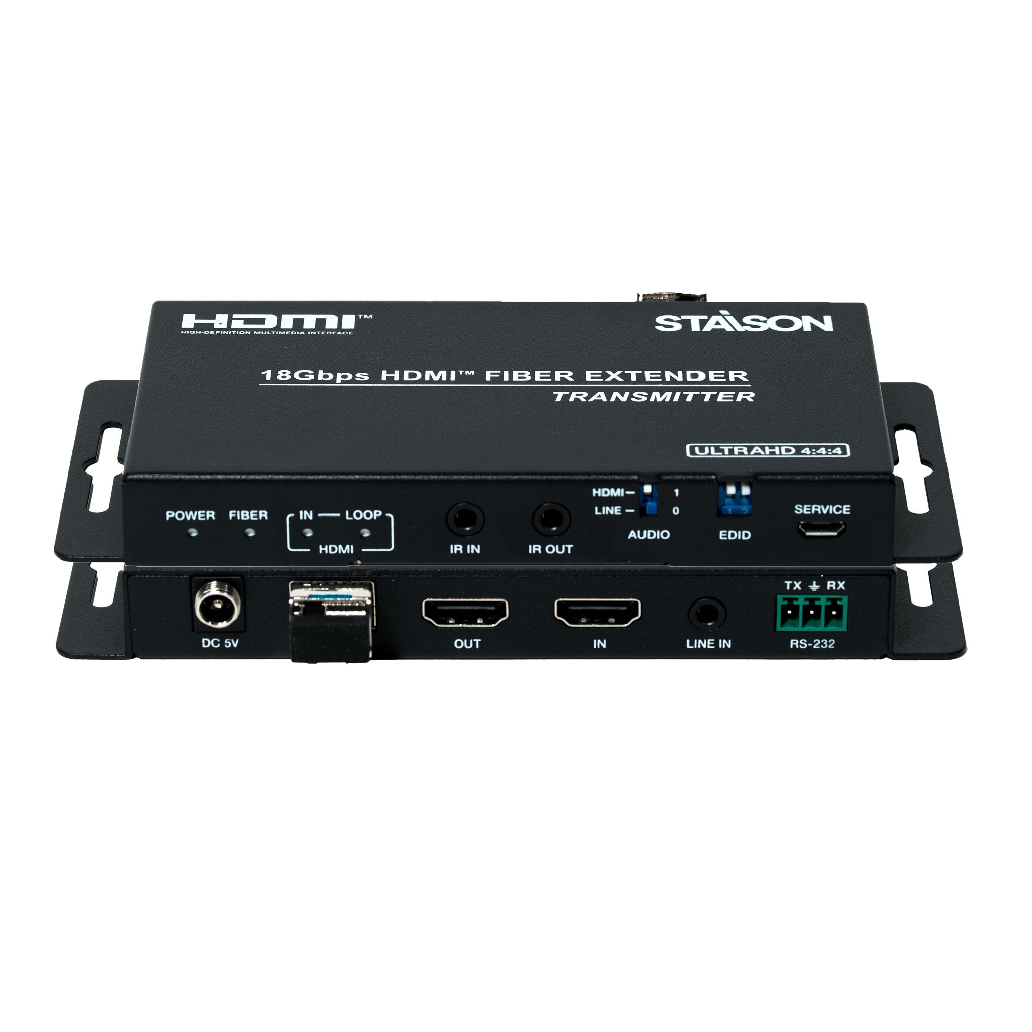
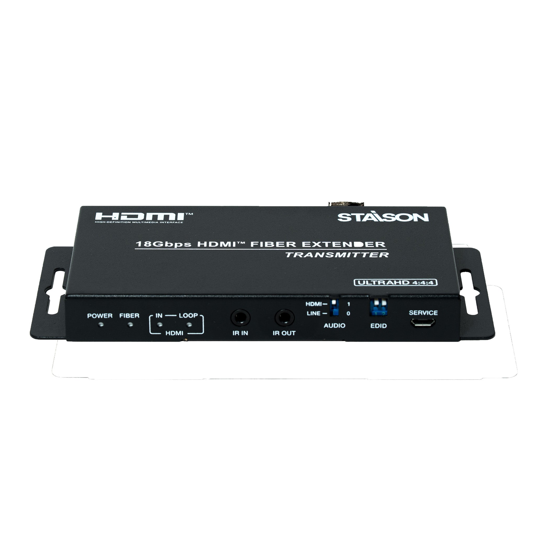
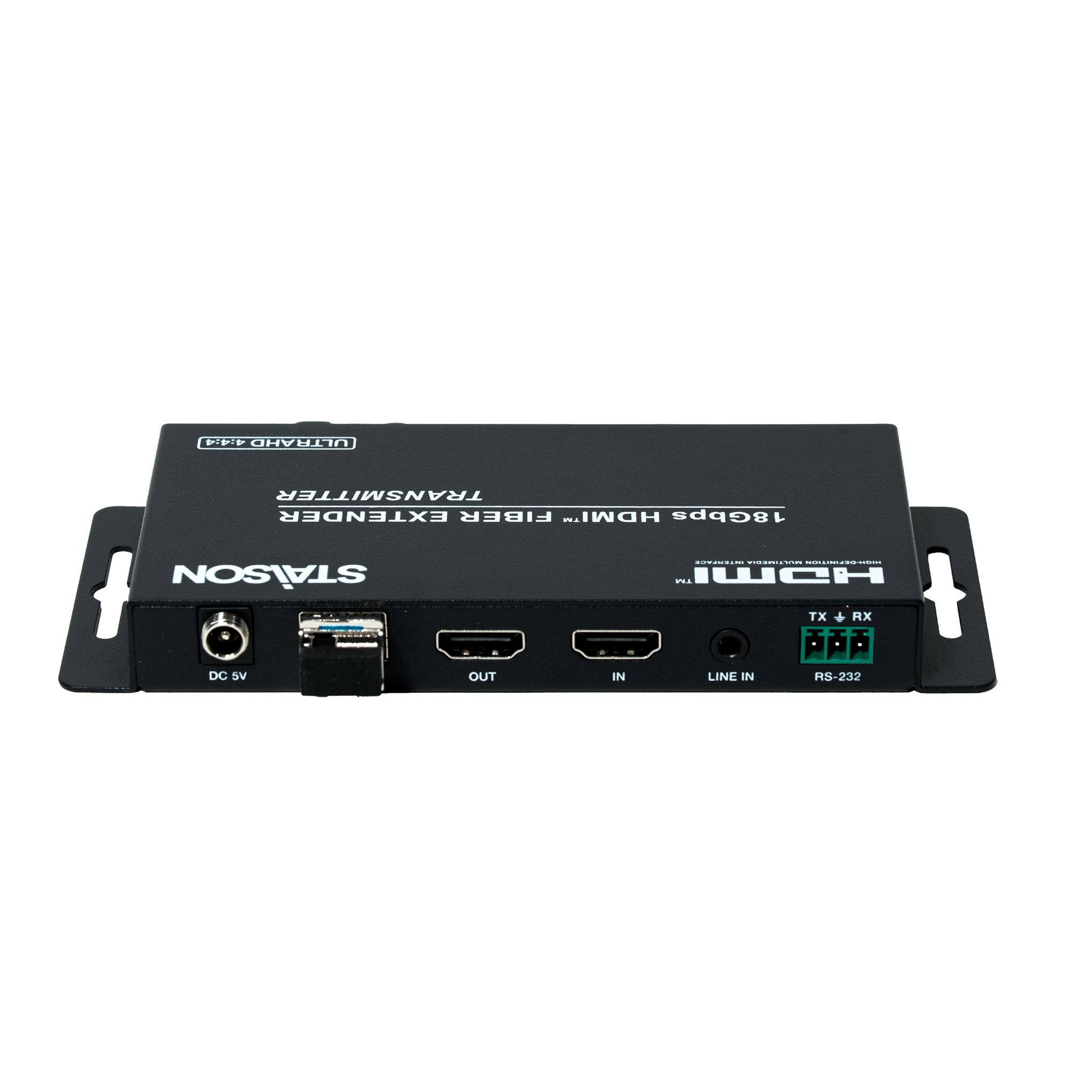
Transmitter Panel

| No. | Name | Function Description |
|---|---|---|
| 1 | POWER LED | The power indicator is always on when the Transmitter is powered on. |
| 2 | FIBER LED | The optical fiber connection indicator is always on when the Transmitter and Receiver establish a normal optical fiber signal connection. |
| 3 | HDMI LED | IN: The HDMI signal input indicator is always on when there is signal input on the HDMI IN port. LOOP: The HDMI loop output indicator is always on when the HDMI OUT port of the Transmitter outputs signals to the HDMI display device. |
| 4 | IR IN | Connect to IR Receiver cable. The IR signal will be sent to the IR OUT port of the Receiver. |
| 5 | IR OUT | Connect to IR Blaster cable. The IR signal is from the IR IN port of the Receiver. |
| 6 | DC 5V | DC 5V/1A power input port. |
| 7 | FIBER OUT | Connect the Transmitter optical fiber module, and transmit signals to the Receiver via an optical fiber cable. |
| 8 | IN | HDMI signal input port, connected to HDMI source device such as DVD or PC with an HDMI cable. |
| 9 | OUT | HDMI signal loop output port, connected to HDMI display device such as TV or Projector with an HDMI cable. |
| 10 | LINE IN | Audio signal input port, connected to audio source device such as MP3. |
| 11 | AUDIO switch | Switch to select audio signal source (HDMI IN or LINE IN). When there is no video signal input, audio signals can be transmitted separately. |
| 12 | EDID DIP switch | Dial the switch to set EDID. 11: Copy RX HDMI OUT 10: Copy TX HDMI LOOP OUT 01: 4K60_2CH 00: 1080P_2CH |
| 13 | SERVICE port | Firmware update port. |
| 14 | RS-232 | RS-232 signal pass-through port for transmitting RS-232 command signals between the Transmitter and Receiver. |
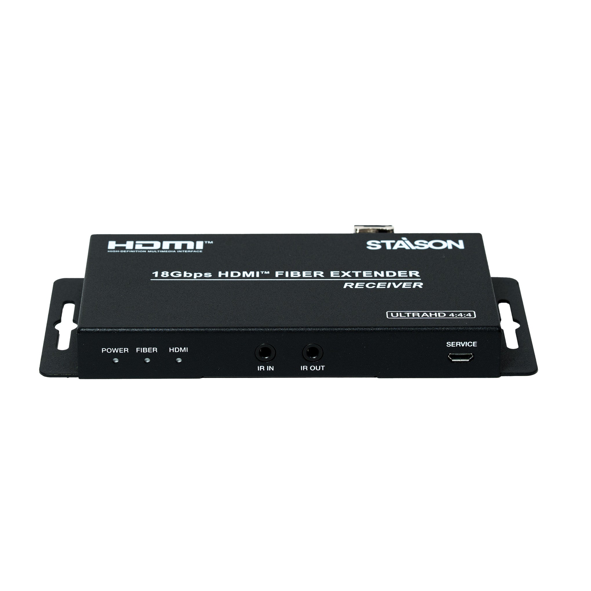
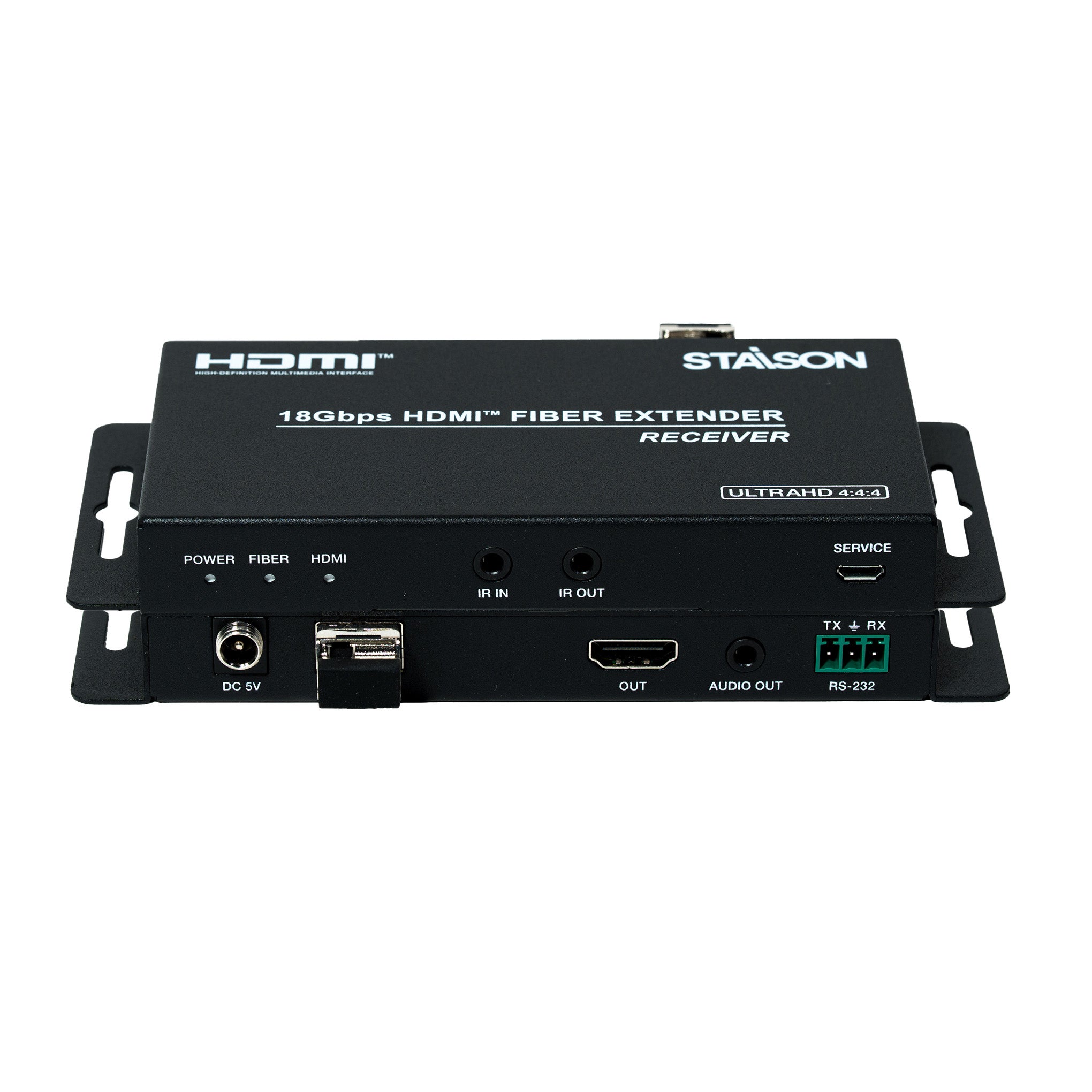
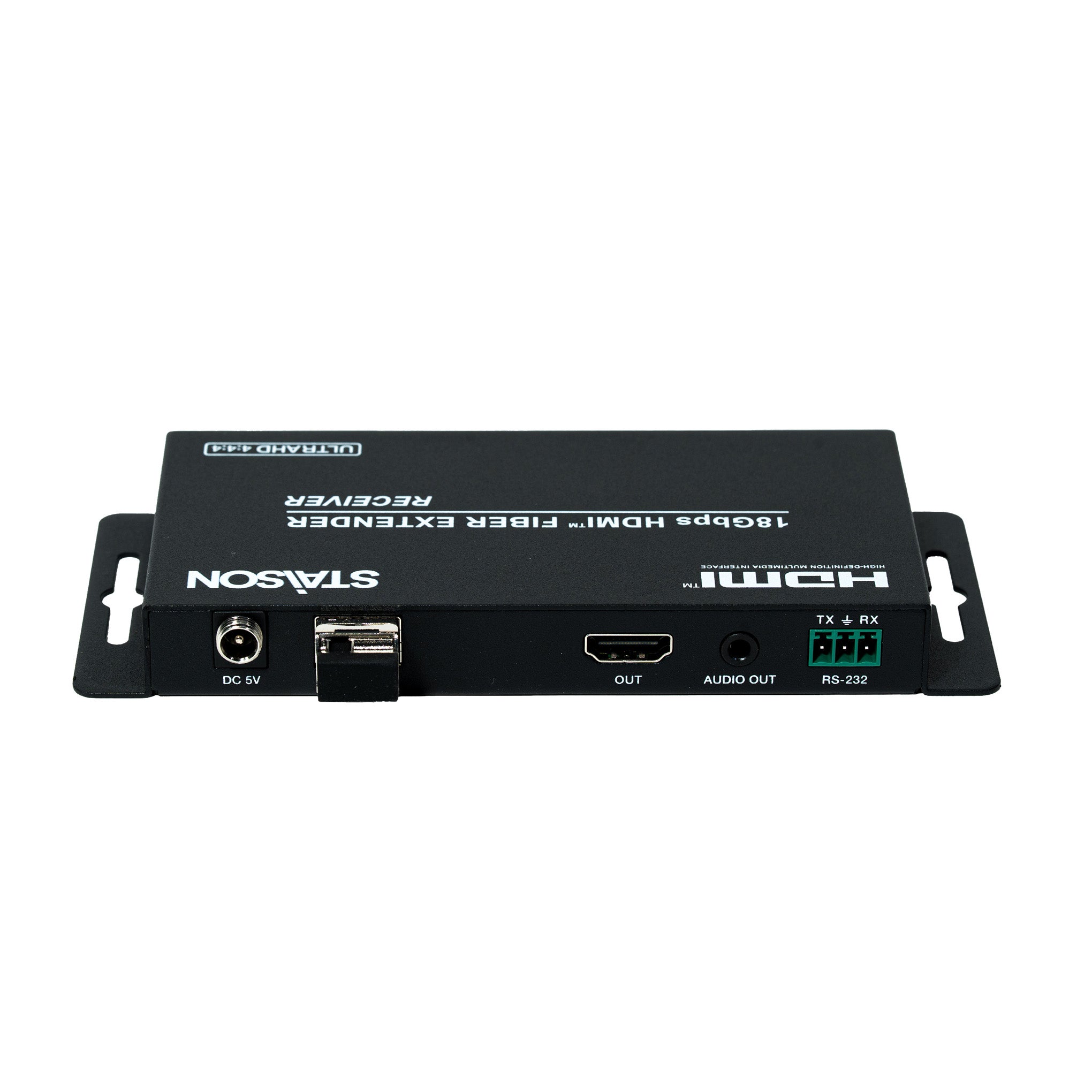
Receiver Panel

| No. | Name | Function Description |
|---|---|---|
| 1 | POWER LED | The power indicator is always on when the Receiver is powered on. |
| 2 | FIBER LED | The optical fiber connection indicator is always on when the Transmitter and Receiver establish a normal optical fiber signal connection. |
| 3 | HDMI LED | The HDMI signal output indicator is always on when the HDMI OUT port of the Receiver outputs signals to the HDMI display device. |
| 4 | IR IN | Connect to IR Receiver cable. The IR signal will be sent to the IR OUT port of the Transmitter. |
| 5 | IR OUT | Connect to IR Blaster cable. The IR signal is from the IR IN port of the Transmitter. |
| 6 | SERVICE port | Firmware update port. |
| 7 | DC 5V | DC 5V/1A power supply port. |
| 8 | FIBER IN | Connect the Receiver optical fiber module, and receive signals from the Transmitter via an optical fiber cable. |
| 9 | OUT | HDMI signal output port, connected to HDMI display device such as HDTV or Projector with an HDMI cable. |
| 10 | AUDIO OUT | Audio signal extracting output port (extracts the HDMI OUT audio signal), connected to audio output device such as amplifier or speaker. |
| 11 | RS-232 | RS-232 signal pass-through port for transmitting RS-232 command signals between the Transmitter and Receiver. |
IR Pin Definition
IR Receiver and Blaster pin definition as below:

Optical Fiber Module

| No. | Module |
|---|---|
| 1 | SFP-BL32TG-10DC is the optical fiber module of the Transmitter. |
| 2 | SFP-BL23TG-10DC is the optical fiber module of the Receiver. |
Application Example
