


Description
This 18Gbps HDBaseT Extender can extend HDMI signal, bi-directional IR control signal and USB KVM signal to a distance up to 492ft/150m (Long Reach Mode) via a single CAT6 cable. This product converts HDMI signal to standard HDBaseT signal and transmits it through LAN cable. It can easily control signal source device or display device from the remote end through bi-directional IR signal pass-through function. Video resolution is up to 4K2K@60Hz YUV 4:4:4. It also supports POC function.
The extender can be widely used in other fields such as video conference system, multimedia signal broadcasting, HDMI signal extension, etc.
Features
☆ HDMI 2.0b and HDCP 2.2 compliant
☆ Support 18Gbps video bandwidth
☆ Support video resolution up to 4K2K@60Hz YUV 4:4:4
☆ With Mode DIP switch to select HDBaseT Mode & Long Reach Mode:
HDBaseT Mode: USB supports USB 2.0 transmission (supports connecting with USB camera, USB flash drive and other devices); the audio & video signal transmission distance can be extended up to 328ft/100m for 4K60.
Long Reach Mode: USB only supports HID (Human Interface Device) devices; the audio & video signal transmission distance can be extended up to 492ft/150m for 1080P or 394ft/120m for 4K60.
☆ Bi-directional IR signal and USB KVM signal pass-through are supported
☆ Support bi-directional POC (Power over Cable) function
☆ Advanced EDID management
☆ Compact design for easy and flexible installation
Package Contents
① 1× 18Gbps HDBaseT Extender (Transmitter)
② 1× 18Gbps HDBaseT Extender (Receiver)
③ 1× IR Blaster cable (1.5 meters)
④ 1× IR Wideband Receiver cable (1.5 meters)
⑤ 4× Mounting Ears
⑥ 8× Machine Screws (KM3*4)
⑦ 1× 24V/1A Locking Power Supply
⑧ 1× User Manual
Specifications
| Parameter | Value |
|---|---|
| Technical | |
| HDMI Compliance | HDMI 2.0b |
| HDCP Compliance | HDCP 2.2 |
| USB Compliance | USB 2.0 |
| Video Bandwidth | 18Gbps |
| Video Resolution | Up to 4K2K@60Hz YUV 4:4:4 |
| Color Depth | 8/10/12-bit |
| Color Space | RGB 4:4:4, YCbCr 4:4:4, YCbCr 4:2:2, YCbCr 4:2:0 |
| HDR | HDR, HDR10, HDR10+, Dolby Vision, HLG |
| Audio Format | LPCM 7.1CH, Dolby TrueHD and DTS-HD Master |
| IR Level | 5Vp-p |
| IR Frequency | Wideband 20K–60KHz |
| ESD Protection | Human body model — ±8kV (Air-gap discharge) & ±4kV (Contact discharge) |
| Transmission | |
| Transmission Distance |
HDBaseT Mode: 4K60 — 328ft / 100m Long Reach Mode: 1080P — 492ft / 150m; 4K60 — 394ft / 120m |
| Connection – Transmitter | |
| Input |
1× HDMI IN [Type A, 19-pin female] 1× IR IN [3.5mm Stereo Mini-jack] 1× SERVICE [Micro-USB jack] 1× USB [USB-B, 4-pin female] |
| Output |
1× HDBT OUT [RJ45] 1× IR OUT [3.5mm Stereo Mini-jack] |
| Connection – Receiver | |
| Input |
1× HDBT IN [RJ45 with light] 1× IR IN [3.5mm Stereo Mini-jack] 1× SERVICE [Micro-USB jack] |
| Output |
1× HDMI OUT [Type A, 19-pin female] 1× IR OUT [3.5mm Stereo Mini-jack] 2× USB 2.0 [USB-A, 4-pin female] |
| Mechanical | |
| Dimensions | Transmitter / Receiver: 140mm (W) × 65mm (D) × 18mm (H) |
| Housing | Metal Enclosure |
| Color | Black |
| Weight | Transmitter: 245g; Receiver: 249g |
| Power & Environmental | |
| Power Supply | DC 24V/1A; Supports bi-directional POC function |
| Power Consumption | 13.2W (Max) |
| Operating Temperature | 0°C ~ 40°C / 32°F ~ 104°F |
| Storage Temperature | -20°C ~ 60°C / -4°F ~ 140°F |
| Relative Humidity | 20~90% RH (non-condensing) |
Operation Controls and Functions
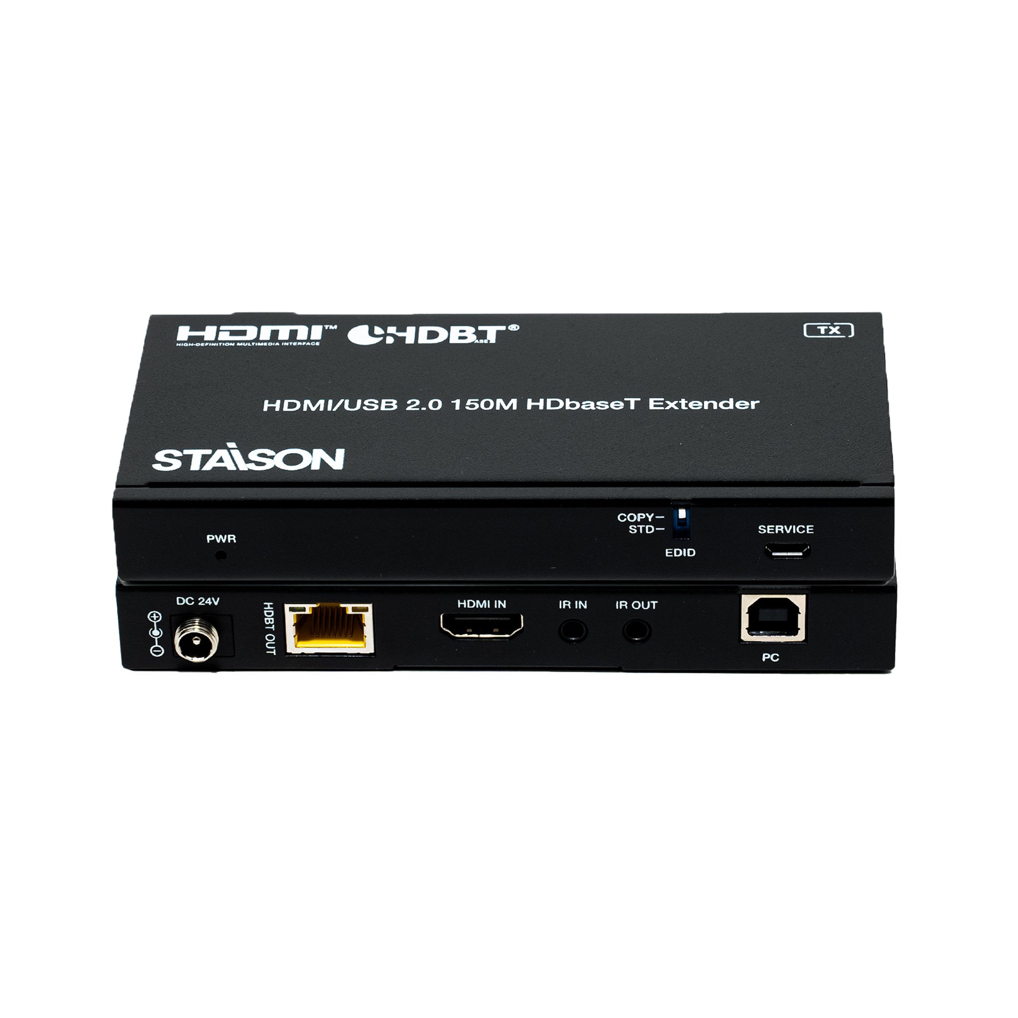
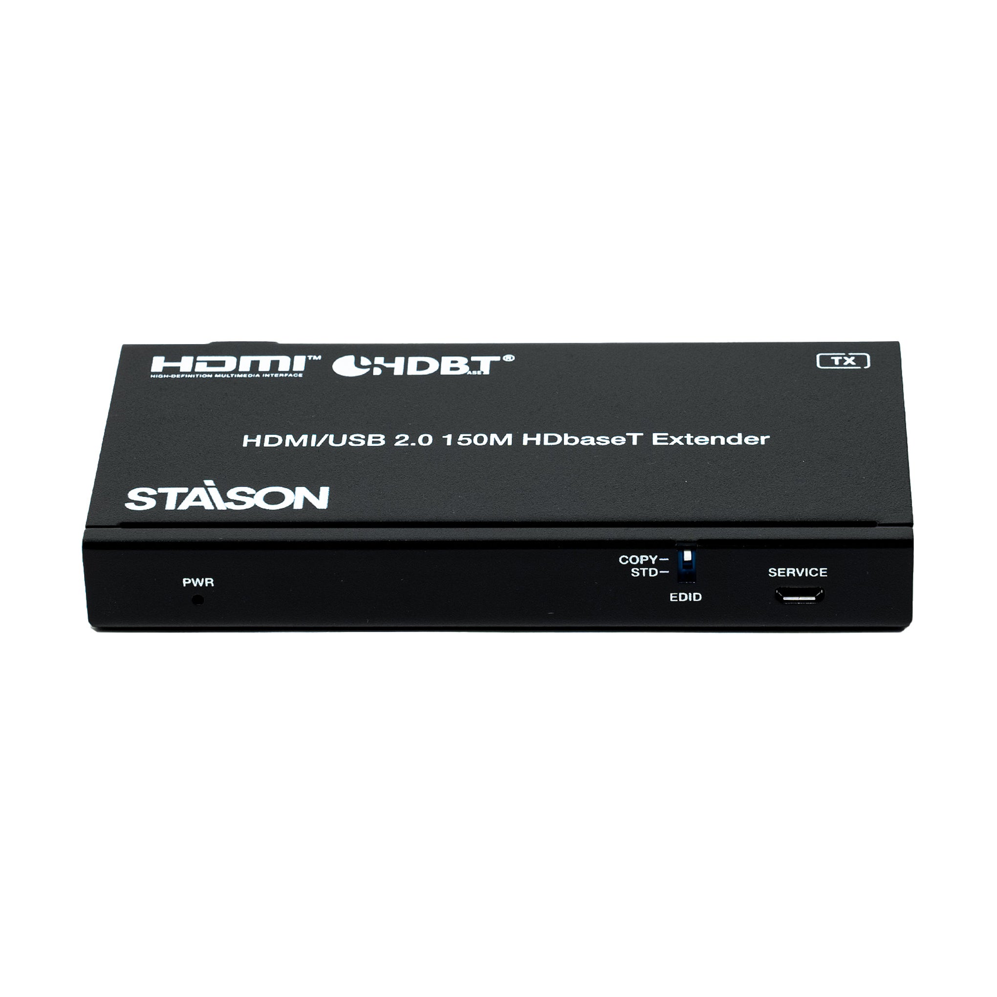
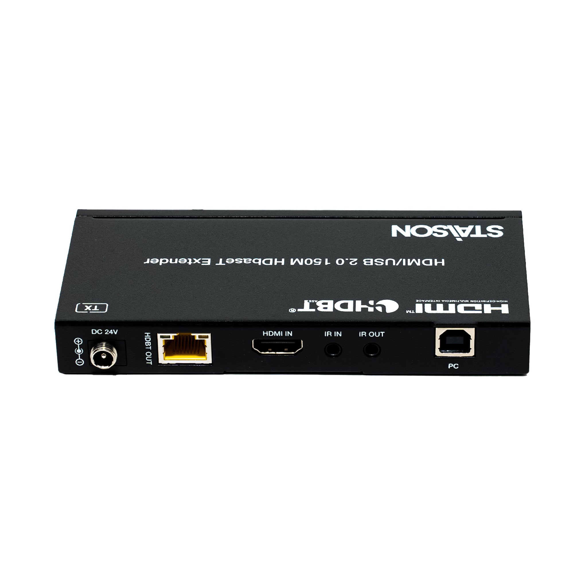
Transmitter Panel

| No. | Name | Function Description |
|---|---|---|
| 1 | PWR LED | The red LED is on when the Transmitter is powered on. |
| 2 | EDID DIP switch | Used for audio EDID setting (dial to COPY by default). COPY: Copy the EDID of the HDMI OUT port of Receiver. STD: Default 1080P 2CH |
| 3 | SERVICE | Firmware update port. |
| 4 | DC 24V | DC 24V/1A power input port. Note: The extender supports POC function — either the Transmitter or Receiver can be connected to the 24V/1A power supply; the other unit does not require a separate power supply. |
| 5 | HDBT OUT | HDBT output port, connecting to the HDBT IN port of the Receiver with CAT6 cable. |
| 6 | Link Signal Indicator (Green) | Illuminating: Transmitter and Receiver are in good connection status. Flashing: Transmitter and Receiver are in poor connection status. Dark: Transmitter and Receiver are not connected. |
| 7 | Data Signal Indicator (Yellow) | Illuminating: HDMI signal with HDCP. Flashing: HDMI signal without HDCP. Dark: No HDMI signal. |
| 8 | HDMI IN | HDMI signal input port, connecting to HDMI source device such as DVD player or Set Top Box. |
| 9 | IR IN | Connect to IR receiver cable. The IR receive signal will be emitted to the IR OUT port of the Receiver. |
| 10 | IR OUT | Connect to IR blaster cable. The IR emit signal is from the IR IN port of the Receiver. |
| 11 | PC | USB-B port, connecting to PC. |
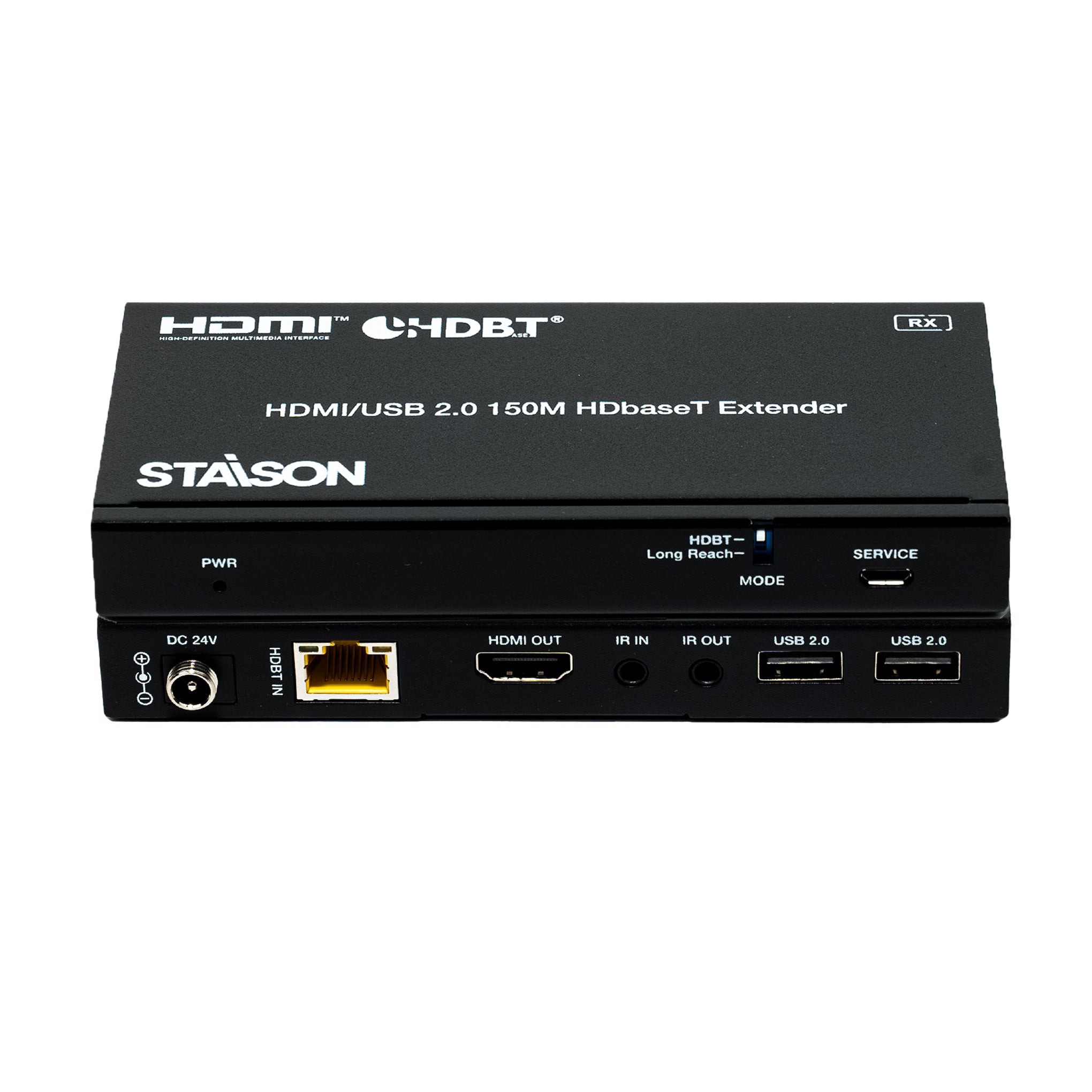
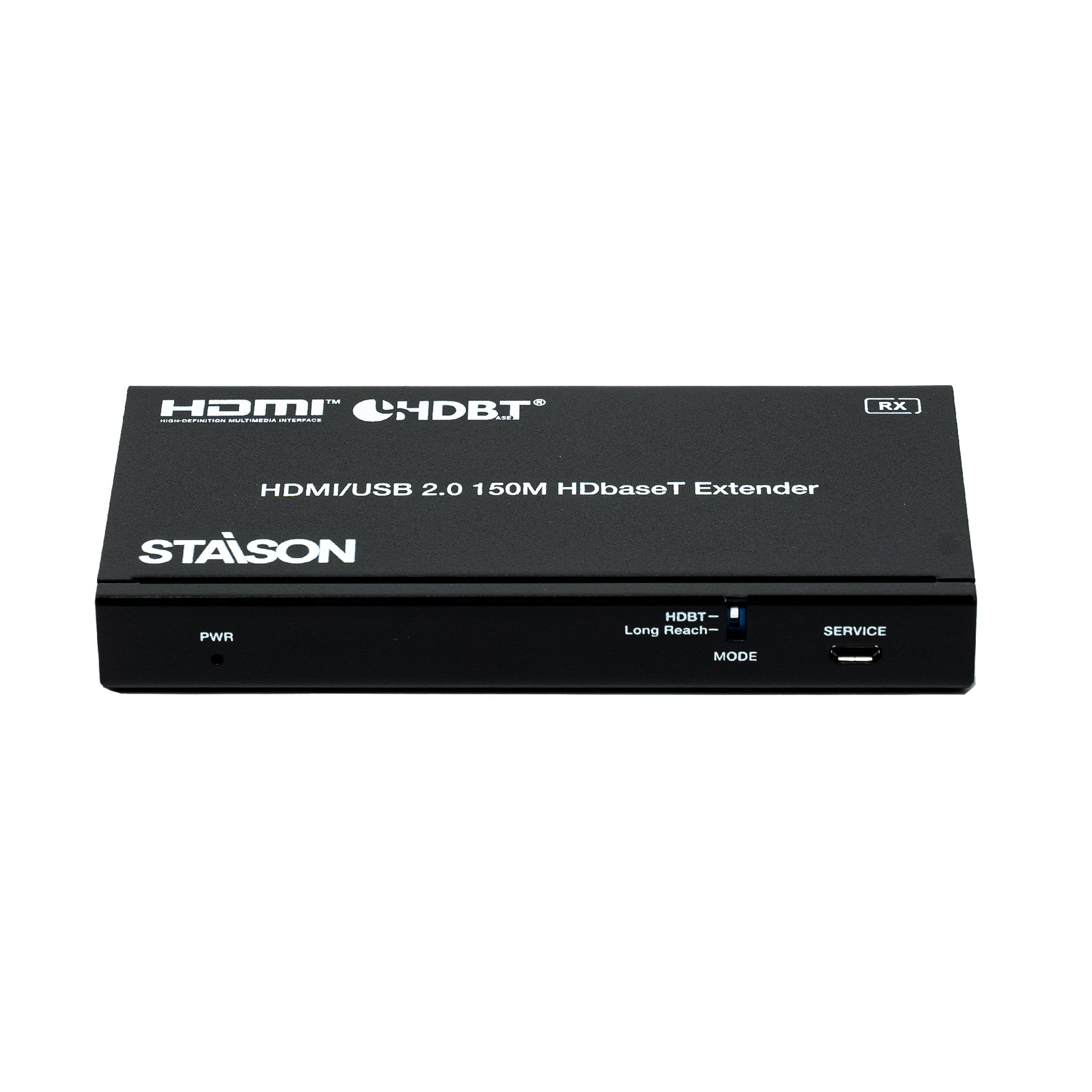
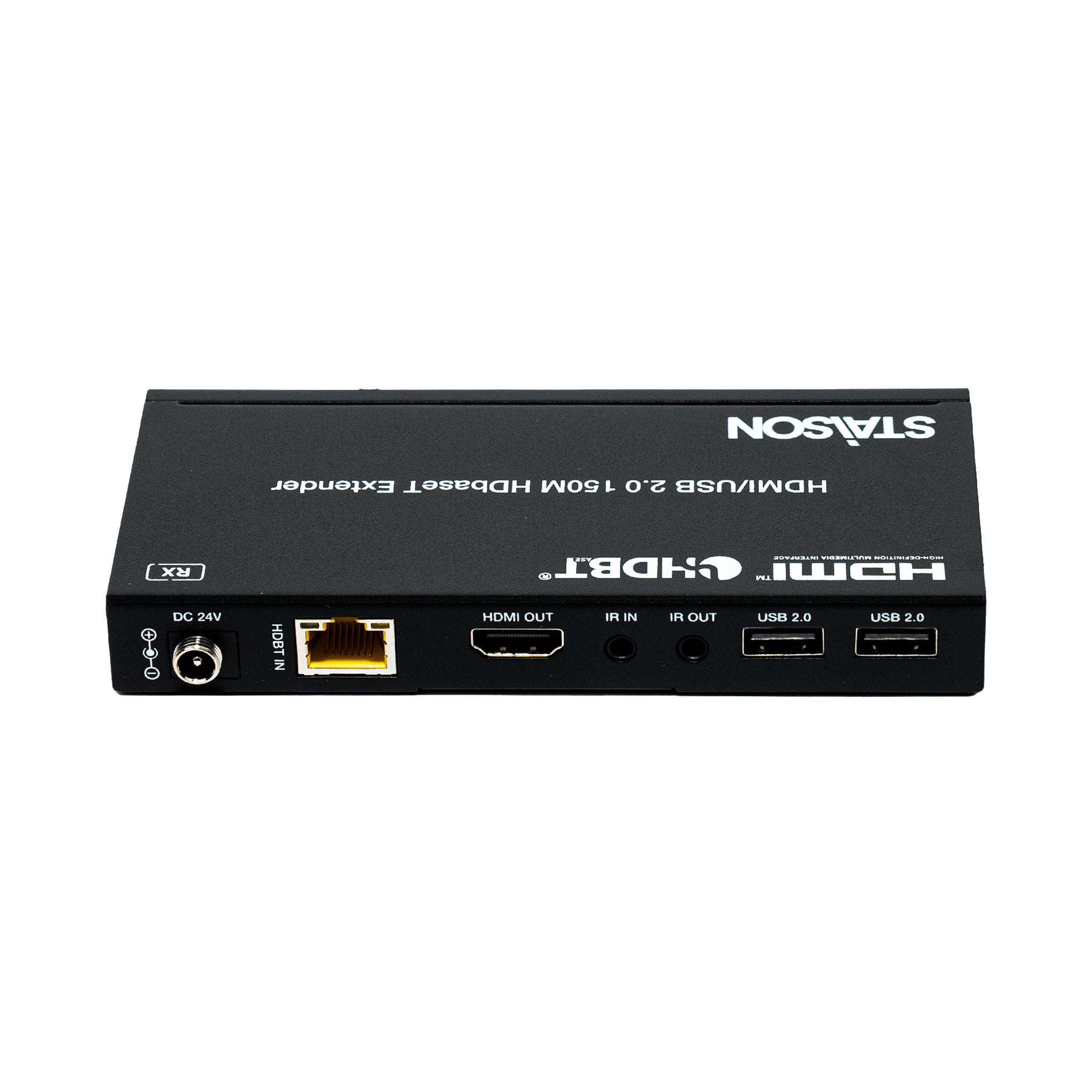
Receiver Panel

| No. | Name | Function Description |
|---|---|---|
| 1 | Power LED | The power LED is on when the Receiver is powered on. |
| 2 | MODE DIP switch | Used for Mode switching (dial to HDBT by default). HDBT: Switch to HDBaseT Mode. Long Reach: Switch to Long Reach Mode. |
| 3 | SERVICE | Firmware update port. |
| 4 | DC 24V | DC 24V/1A power input port. Note: The extender supports POC function — either the Transmitter or Receiver can be connected to the 24V/1A power supply; the other unit does not require a separate power supply. |
| 5 | HDBT IN | HDBT input port, connecting to the HDBT OUT port of the Transmitter with CAT6 cable. |
| 6 | Link Signal Indicator (Green) | Illuminating: Transmitter and Receiver are in good connection status. Flashing: Transmitter and Receiver are in poor connection status. Dark: Transmitter and Receiver are not connected. |
| 7 | Data Signal Indicator (Yellow) | Illuminating: HDMI signal with HDCP. Flashing: HDMI signal without HDCP. Dark: No HDMI signal. |
| 8 | HDMI OUT | HDMI signal output port, connecting to HDMI display device such as TV or monitor. |
| 9 | IR IN | Connect to the IR receiver cable. The IR signal will be sent to the IR OUT port of the Transmitter. |
| 10 | IR OUT | Connect to the IR blaster cable. The IR signal is from the IR IN port of the Transmitter. |
| 11 | USB 2.0 ports | Two USB-A ports, connecting to USB 2.0 devices. (The maximum output current of a single USB 2.0 port is 500mA; exceeding this limit may cause the port to stop working.) |
IR Pin Definition
IR Receiver and Blaster pin definition is as below:

Note:
When the angle between the IR receiver and the remote control is ±45°, the transmission distance is 0–5 meters.
When the angle between the IR receiver and the remote control is ±90°, the transmission distance is 0–8 meters.
Application Example
