


Description
This SDVoE Transceiver with Copper/Fiber Combo Box is an SDVoE-Compliant, All-In-One AV over IP solution providing highest-quality, uncompressed 4K60 and zero-frame latency audio/video extension over a standard 10G Copper or Fiber Network Switch. The flexible transceiver design allows one box to be configured as either Encoder or Decoder — ideal for real installation sites and inventory control. It supports Video Wall, MultiView, seamless switching, bidirectional IR, RS-232, USB KVM, CEC and 1G Ethernet. The built-in Secondary Stream supports H.264/H.265 compression for portable device preview. Standard 802.3at PoE is supported, eliminating the need for a separate power supply when connected to a PoE switch.
Features
☆ HDMI 2.0b and HDCP 2.2 compliant, 18Gbps video bandwidth, up to 4K@60Hz 4:4:4
☆ Flexible transceiver — Encoder or Decoder mode selectable via front panel button or API
☆ Copper (10G BASE-T) and Fiber (SFP+) ports in a single box with automatic port detection (priority configurable)
☆ Encoder supports HDMI loop out; Decoder HDMI output supports video scaling
☆ HDR10, Dolby Vision, HLG, 3D support
☆ LPCM 2/5.1/7.1, Dolby Digital, Dolby Digital+, Dolby TrueHD, Dolby Atmos, DTS 5.1, DTS-HD Master Audio, DTS:X
☆ Zero-Frame latency operating mode
☆ Signal extension, seamless switching, IP Matrix, Video Wall up to 9×9, MultiView up to 25 windows
☆ Flexible bidirectional analog audio routing between Encoder and Decoder
☆ Built-in H.264/H.265 Secondary Stream (SS) for preview on portable devices
☆ Secondary Stream VLAN tagging and parameter configuration
☆ Bi-directional IR and RS-232 control signal pass-through
☆ USB 2.0 KVM support and CEC routing control
☆ IR, RS-232, TCP/IP and Web GUI control
☆ Standard PoE supported (IEEE 802.3at PD device)
☆ Works with 10G managed network switch and IP Controller Box ST-NCTL100D
Package Contents
① 1x SDVoE Transceiver (Copper/Fiber Combo)
② 1x 12V IR Receiver Cable (1.5 metres)
③ 1x IR Blaster Cable (1.5 metres)
④ 1x 4pin-3.81mm Phoenix Connector
⑤ 1x 12V/2.5A Locking Power Adapter
⑥ 2x Mounting Ears
⑦ 4x Machine Screws (KM3×6)
⑧ 1x User Manual
Note: Three MAC address labels are on the back of the product. MAC 1 = SDVoE MAC address · MAC 2 = USB 2.0 MAC address · MAC 3 = Secondary Stream (SS) Module MAC address.
Specifications
| Technical | |
| HDMI Compliance | HDMI 2.0b |
| HDCP Compliance | HDCP 2.2 |
| Video Bandwidth | 18Gbps |
| Video Resolution | Up to 4K@60Hz 4:4:4 |
| Color Space | RGB, YCbCr 4:4:4 / 4:2:2 / 4:2:0 |
| HDR | HDR, HDR10, HDR10+, Dolby Vision, HLG |
| HDMI Audio | LPCM, Dolby Digital/Plus/EX, Dolby TrueHD, Dolby Atmos, DTS, DTS-EX, DTS-96/24, DTS High Res, DTS-HD Master Audio, DSD, DTS:X |
| Analog Audio | Left and Right stereo analog audio (3.5mm jack) |
| ESD Protection | ±8kV (Air-gap discharge), ±4kV (Contact discharge) |
| Network | |
| Video Network Bandwidth | 10G |
| Copper Transmission Distance | 100m (CAT6A/CAT7) / 70m (CAT6) |
| HDMI Cable Length | 4K60: 5m / 16ft | 4K30: 10m / 32ft | 1080p60: 15m / 50ft |
| Input Ports | |
| HDMI IN | 1x [HDMI Type A, 19-pin female] |
| USB HOST | 1x USB 2.0 [Type B, 4-pin female] |
| IR IN | 1x [3.5mm jack] |
| AUDIO IN | 1x [3.5mm jack] |
| RS-232 | 1x [4pin-3.81mm Phoenix connector] |
| Output Ports | |
| HDMI OUT | 1x [HDMI Type A, 19-pin female] |
| AUDIO OUT | 1x [3.5mm jack] |
| IR OUT | 1x [3.5mm jack] |
| USB DEVICES | 2x USB 2.0 [Type A, 4-pin female] |
| Network Ports | |
| 10G BASE-T | 1x [RJ45 jack] |
| SFP+ | 1x [Fiber slot, 10G] |
| 1G LAN | 1x [RJ45 jack] |
| Mechanical | |
| Housing | Metal Enclosure — Black |
| Dimensions | 204mm [W] × 134mm [D] × 21.5mm [H] |
| Weight | 693g |
| Power Supply | Input: AC100–240V 50/60Hz; Output: DC 12V/2.5A (CE/FCC/UL certified) Also supports IEEE 802.3at PoE (PD device) |
| Power Consumption (Max) | ≈13.5W |
| Operating Temperature | 0°C ~ 40°C / 32°F ~ 104°F |
| Storage Temperature | -20°C ~ 60°C / -4°F ~ 140°F |
| Operating Humidity | 20%~90% (relative humidity, non-condensing) |
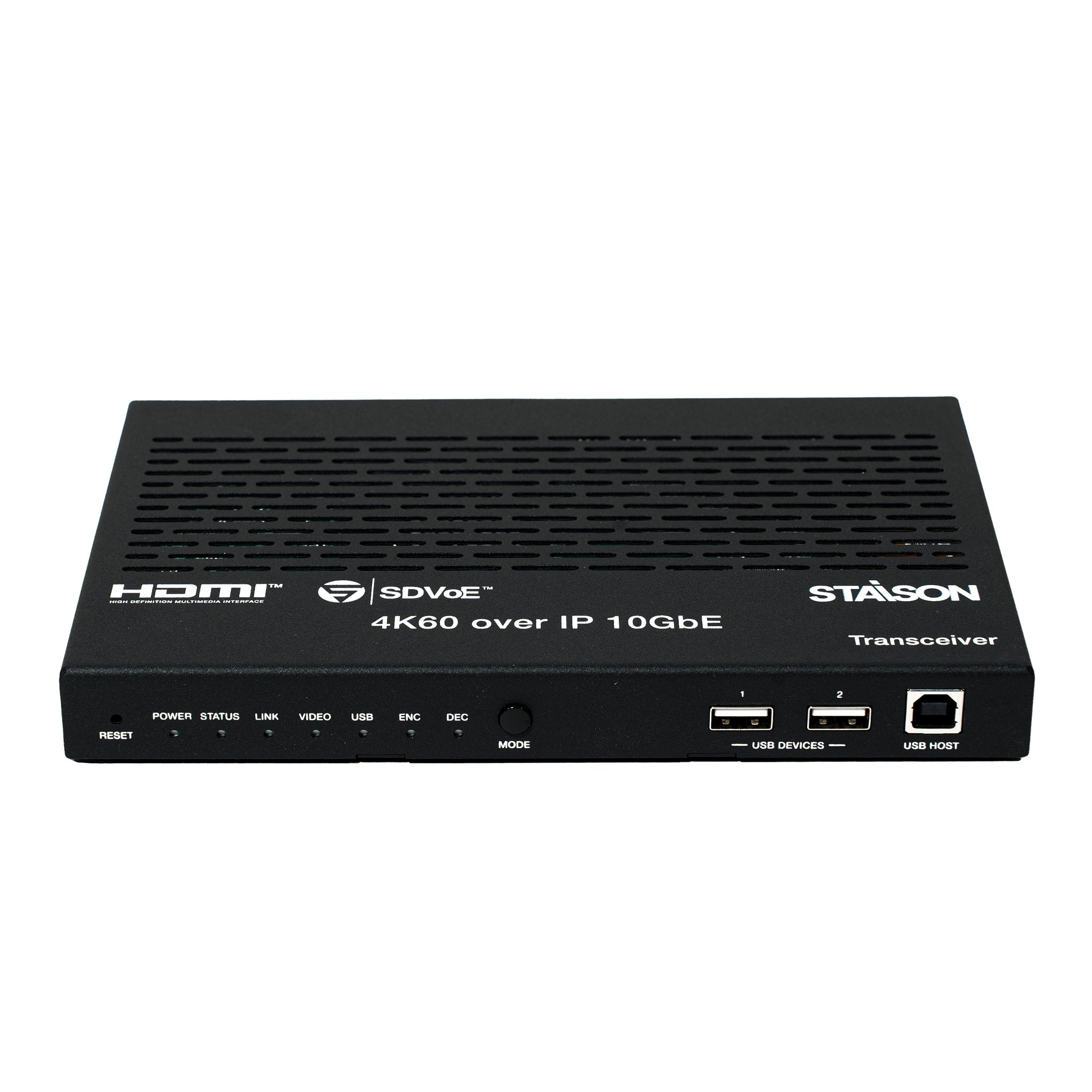
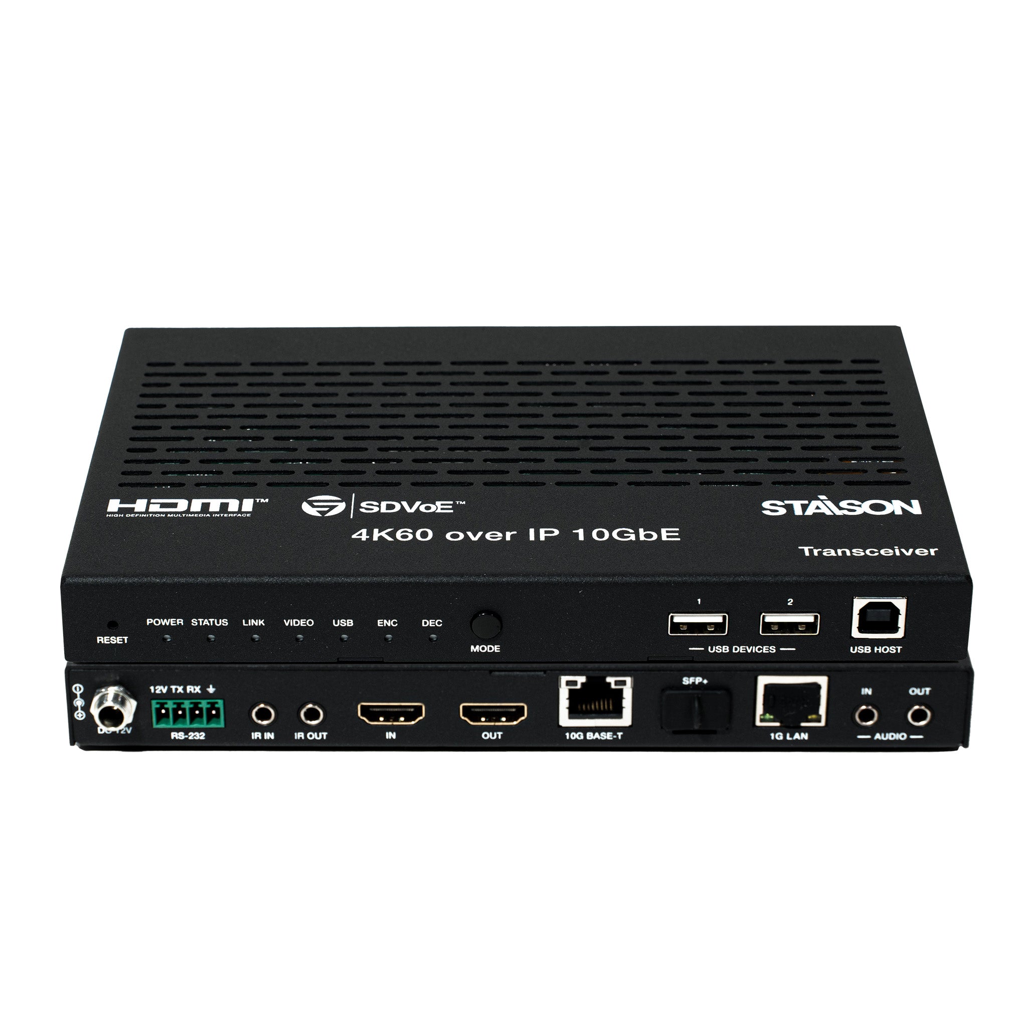
Operation Controls and Functions
Front Panel

| No. | Name | Function Description |
|---|---|---|
| 1 | RESET Button | Press and hold for 5 seconds while powered on to restore factory default settings. |
| 2 | POWER LED (Red) | On when unit is powered on. Off when powered off. |
| 3 | STATUS LED (Green) | On: System running normally. Flashing or Off: Firmware issue or hardware error. |
| 4 | LINK LED (Green) | On: 10G network port connected. Off: 10G network port not connected. |
| 5 | VIDEO LED (Green) | ENC mode: On = video input detected on HDMI IN. DEC mode: On = HDMI OUT has active video output. |
| 6 | USB LED (Green) | Flashing: USB devices connected with active data transmission. Off: No USB devices connected. |
| 7 | ENC LED (Green) | Always on when device is in Encoder mode. On startup, flashes ~15 seconds then stays on. After a mode switch, flashes ~30 seconds then stays on. |
| 8 | DEC LED (Green) | Always on when device is in Decoder mode. Same startup/switch behaviour as ENC LED. Also flashes in SHOW ME mode (activated via Controller Box) to identify the physical device. |
| 9 | MODE Button | Press and hold for 5 seconds to switch between ENC and DEC mode. The corresponding LED flashes ~30 seconds then stays on to confirm the mode switch. |
| 10 | USB DEVICES Ports | 2x USB 2.0 Type-A ports. Connect mouse, keyboard or USB storage when product is in DEC mode. |
| 11 | USB HOST Port | USB 2.0 Type-B port. Connect to PC when product is in ENC mode. |
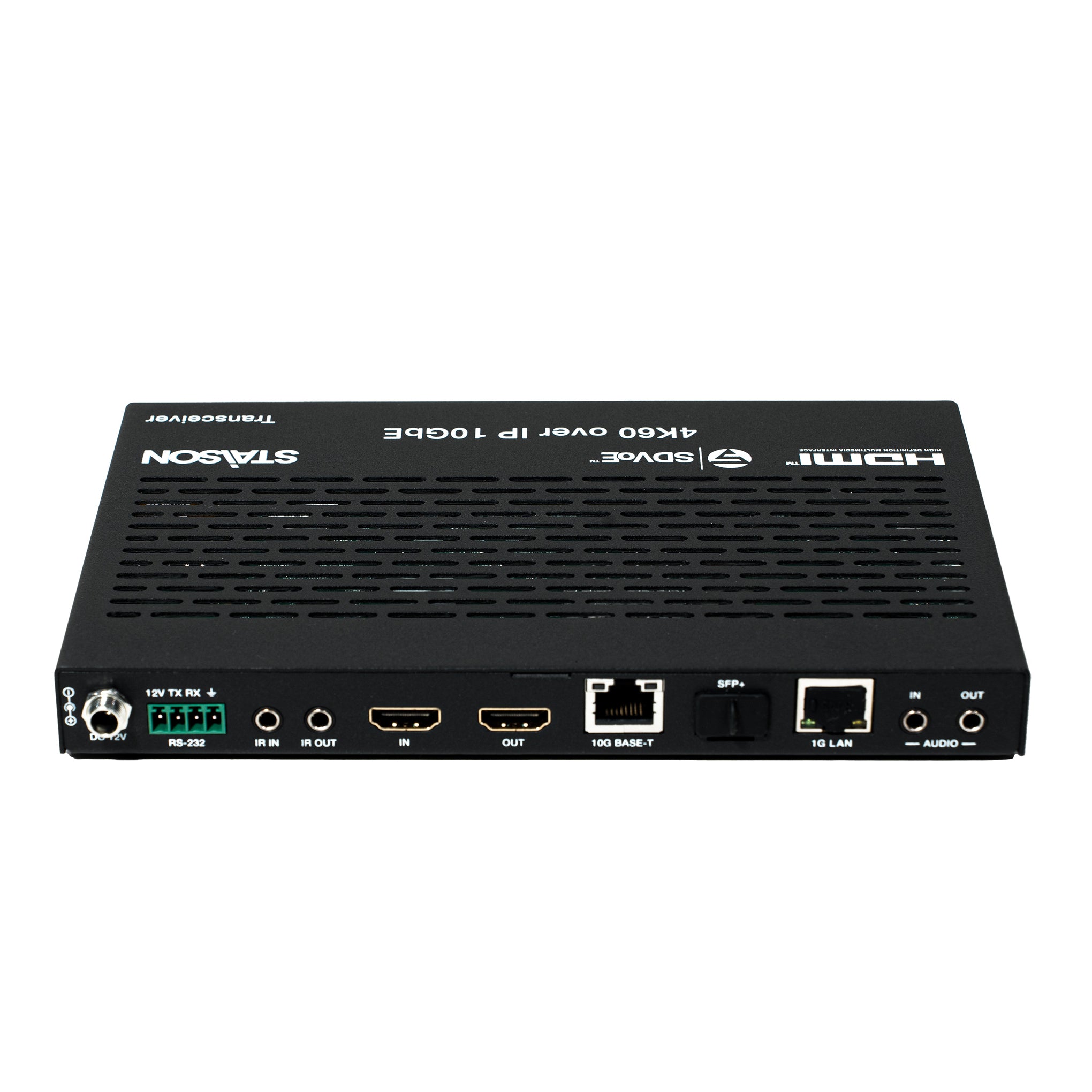
Rear Panel

| No. | Name | Function Description |
|---|---|---|
| 1 | DC 12V Port | DC 12V/2.5A locking power input port. |
| 2 | RS-232 Port | Connect to PC or control system via 4pin-3.81mm phoenix connector for RS-232 signal pass-through. Pin assignment: 12V · TX · RX. The 12V pin supplies power to the peripheral. |
| 3 | IR IN Port | IR signal input port. Connect the included 12V IR Receiver cable. Pin 1: IR Signal, Pin 2: Ground, Pin 3: 12V Power. |
| 4 | IR OUT Port | IR signal output port. Connect the included IR Blaster cable. Pin 1: +, Pin 2: −. |
| 5 | HDMI IN Port | HDMI signal input port — used in ENC mode. Connect to HDMI source device (DVD, set-top box) with HDMI cable. |
| 6 | HDMI OUT Port | ENC mode: Loop output of the HDMI IN signal to a local display. DEC mode: Outputs the remote Encoder video stream to a connected display. |
| 7 | 10G BASE-T Port | 10G copper network port (RJ45). Connect to 10G Switch for video transmission. Supports 100m (CAT6A/CAT7) or 70m (CAT6). |
| 8 | SFP+ Port | 10G fiber optical port. Connect to 10G Switch via SFP+ fiber module for video transmission. |
| 9 | 1G LAN Port | 1G network port for management or Secondary Stream (SS) transmission. |
| 10 | AUDIO IN Port | Analog stereo audio input (3.5mm jack) — for analog audio pass-through, Secondary Stream audio embedding, and HDMI audio embedding. |
| 11 | AUDIO OUT Port | Analog stereo audio output (3.5mm jack) — outputs HDMI extracted stereo audio or remote analog audio signal. |
IR Pin Definition

Rack Mounting
This transceiver can be mounted in a standard 6U rack (Please contact your
supplier for 6U rack sale). The mounting steps are as follows:
Step 1: Use included screws to fix two mounting ears on the transceiver, as
shown in the figure below:

Step 2: Insert the transceiver with mounting ears into a 6U rack (up to 10
units can be installed vertically), as shown in the figure below:

Step 3: Use screws to fix mounting ears on the rack to complete the mounting,
as shown in the figure below:

1U Rack Mounting
This transceiver also can be mounted in a standard 1U rack (up to 4 units can
be installed horizontally). The mounting steps are as follows:
Step 1: Stack two transceivers on top of each other, then use included screws
to fix two 1U rack panels on the transceivers, as shown in the figure below:

Step 2: Fix two 1U rack panels on another two stacked transceivers in the
same way, then use screws to fix two 1U rack panels together, as shown in
the figure below: 
Step 3: Fasten screws between two 1U rack panels, so that four transceivers
are mounted in a 1U rack, as shown in the figure below:

Network Switch Requirements
The network switch must support all of the following: Layer 3 / Managed, 10 Gigabit bandwidth, IGMP v2 supported and snooping enabled, filter/drop unregistered multicast traffic, disable unregistered multicast flooding, enable fast leave support.
Recommended switch models: Netgear ProSAFE PLUS XS708E, Netgear ProSAFE Smart XS712T, Netgear M7300-24XF XSM7224S, Netgear ProSAFE M4300 Intelligent Edge Series, Arista Networks 7050X Series.
SDVoE System Control
This transceiver can be controlled by a Controller Box (ST-NCTL100D) or a third-party controller. When the network switch does not support PoE, the units must be powered by the DC power adapter. Controller Box Control LAN default mode is DHCP. If no DHCP server is present, the Control LAN defaults to 192.168.0.225 — set PC to the same subnet (e.g. 192.168.0.88). Access the Web GUI at http://controller.local or http://192.168.0.225.
Application Example
