


Description
The ST-NEHB100CN HDBaseT Extender can transmit HDMI high-definition signal, bi-directional IR control signal, bi-directional RS-232 control signal and USB 2.0 signal over CAT6 cable up to 100m in HBT mode or 150m in LRM mode. The ST-NEHB100CN HDBaseT Extender supports 4K2K@60Hz 4:4:4 video, audio embedding, audio de-embedding, EDID management and POC function. The ST-NEHB100CN HDBaseT Extender is suitable for video conference systems, multimedia broadcasting, HDMI signal extension and professional AV installations.
The ST-NEHB100CN HDBaseT Extender can be widely used in other fields such as video conference system, multimedia signal broadcasting, HDMI signal extension, etc.
The ST-NEHB100CN HDBaseT Extender delivers reliable HDMI, USB 2.0, IR and RS-232 signal transmission over long distances.
Features
☆ HDMI 2.0b and HDCP 2.2/1.x compliant
☆ Support video resolution up to 4K2K@60Hz (4:4:4), 18Gbps video bandwidth
☆ Up to 7.1 channels HD audio
☆ Built-in mode DIP switch for selecting the HBT mode or LRM mode:
HBT mode: Audio and video signals can be transmitted up to 328ft/100m for 4K60/4K30/1080P.
LRM mode: Audio and video signals can be transmitted up to 492ft/150m for 4K30/1080P.
☆ Built-in EDID DIP switch supports intelligent EDID management
☆ Built-in audio DIP switch supports analog audio embedding
☆ Built-in POC switches — when both POC switches of TX and RX are turned on, the Extender supports bidirectional 24V POC function; either TX or RX is powered by 24V/1A power supply, the other does not need power supply from the DC jack
☆ Transmit bidirectional Infrared control signal together with the HDMI signal (IR IN is a 5V power supply level)
☆ Transmit bidirectional RS-232 control signal together with the HDMI signal
☆ Supports USB 2.0 signal transmission
☆ Compact design for easy and flexible installation
Package Contents
① 1× 4K60 HDMI/USB 2.0 HDBT Extender (Transmitter)
② 1× HDBT Receiver
③ 4× 3pin-3.81mm Phoenix connector (male)
④ 1× Wideband IR Receiver cable (1.5 meters)
⑤ 1× IR Blaster cable (1.5 meters)
⑥ 4× Mounting Ears
⑦ 8× Machine Screws M3*4
⑧ 1× 24V/1A Locking Power Supply
⑨ 1× User Manual
The ST-NEHB100CN HDBaseT Extender supports 18Gbps bandwidth, 4K60 video and bidirectional 24V POC.
Specifications
| Technical | |
| HDMI Compliance | HDMI 2.0b |
| HDCP Compliance | HDCP 2.2 |
| Video Bandwidth | 18Gbps |
| Video Resolution | Up to 4K2K@60Hz 4:4:4 |
| Color Space | RGB 4:4:4, YCbCr 4:4:4, YCbCr 4:2:2, YCbCr 4:2:0 |
| Color Depth | 8/10/12-bit |
| HDMI Audio Formats | LPCM 7.1CH, Dolby TrueHD and DTS-HD Master (Full format) |
| ESD Protection | IEC 61000-4-2: ±8kV (Air-gap discharge) & ±4kV (Contact discharge) |
| Transmission | |
| STD-HBT Mode | 328ft / 100m (4K@60Hz / 4K@30Hz / 1080P) over CAT6 |
| LRM Mode | 492ft / 150m (4K@30Hz / 1080P) over CAT6 |
| Connection – Transmitter | |
| Input | 1× HDMI IN [Type A, 19-pin female] 1× AUDIO IN [3-pin 3.81mm Phoenix connector] |
| Output | 1× HDMI OUT [Type A, 19-pin female] 1× HDBT OUT [RJ45] |
| Control | 1× TO PC [USB Type B] 1× RS-232 [3-pin 3.81mm Phoenix connector] 1× IR IN [3.5mm Stereo Mini-jack] 1× IR OUT [3.5mm Stereo Mini-jack] 1× SERVICE [Micro USB] |
| Connection – Receiver | |
| Input | 1× HDBT IN [RJ45] |
| Output | 1× HDMI OUT [Type A, 19-pin female] 1× AUDIO OUT [3-pin 3.81mm Phoenix connector] |
| Control | 2× USB 2.0 [USB Type A] 1× RS-232 [3-pin 3.81mm Phoenix connector] 1× IR IN [3.5mm Stereo Mini-jack] 1× IR OUT [3.5mm Stereo Mini-jack] 1× SERVICE [Micro USB] |
| Power | |
| Power Supply | DC 24V/1A (supports bidirectional POC function) |
| Power Consumption | 11.76W (Max) |
| Mechanical | |
| Dimensions | 157.2mm [W] × 88mm [D] × 20mm [H] |
| Weight | Transmitter: 380g | Receiver: 377g |
| Housing | Metal Enclosure – Black |
| Environmental | |
| Operating Temperature | 0°C ~ 40°C / 32°F ~ 104°F |
| Storage Temperature | -20°C ~ 60°C / -4°F ~ 140°F |
| Relative Humidity | 20%~90% RH (non-condensing) |
Operation Controls and Functions
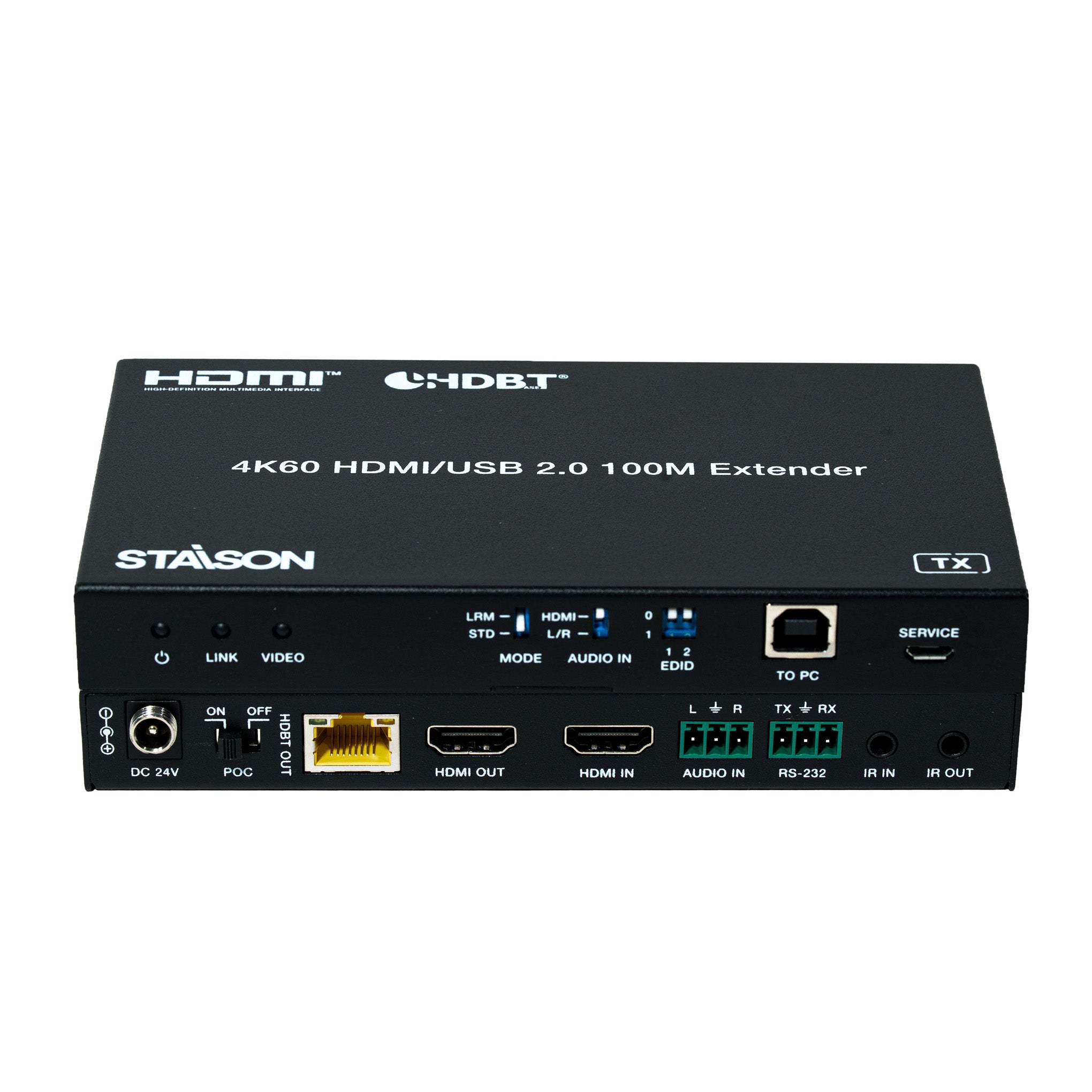
Transmitter Panel

| No. | Name | Function Description |
|---|---|---|
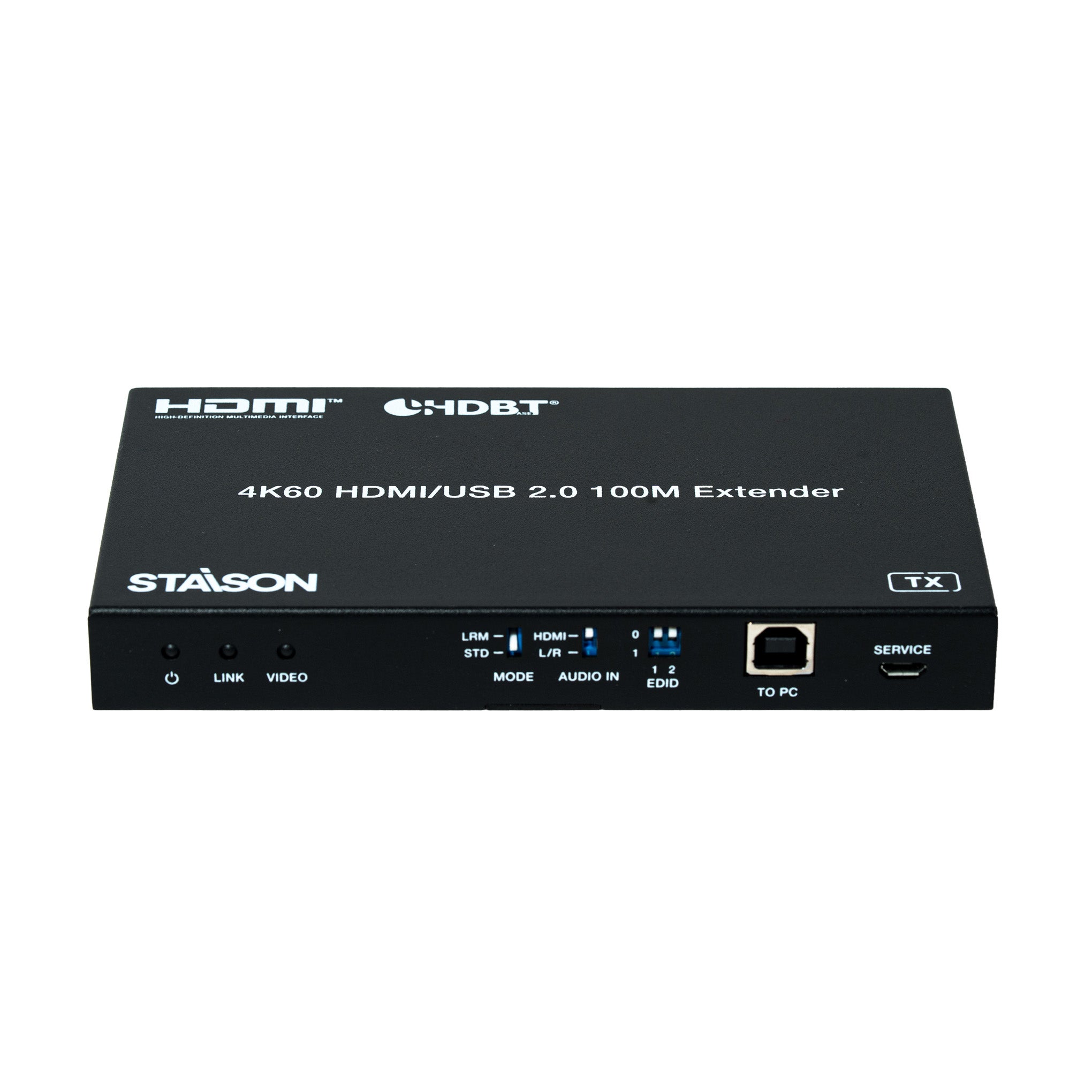
| 1 | Power LED (Red) | Indicates the Transmitter is powered on. |
| 2 | LINK LED (Green) | Light on: Transmitter and Receiver are in good connection status. Light flashing: Transmitter and Receiver are in poor connection status. Light off: Transmitter and Receiver are not connected. |
| 3 | VIDEO LED (Green) | Light flashing: There is valid signal input. Light off: There is no signal or the signal is invalid. |
| 4 | MODE DIP Switch | Used to select the working mode: LRM (Long Reach Mode): Extends signal up to 492ft/150m via a single CAT6 cable. STD-HBT Mode: Extends signal up to 328ft/100m via a single CAT6 cable. |
| 5 | AUDIO IN DIP Switch | Used to select the signal source for the audio output of Receiver: HDMI: Output the de-embedded audio from the HDMI IN port of Transmitter. L/R: Output the analog audio embedded from the AUDIO IN port of Transmitter. |
| 6 | EDID DIP Switch | Used to set the EDID information: 00 — Copy RX display's EDID (factory default) 01 — 4K30 4:4:4 10 — 1080p60 4:4:4 11 — 1200p60 4:4:4 |
| 7 | TO PC Port | USB HOST port, connected to PC. |
| 8 | SERVICE Port | Software update port. Send command "s switch uart 0!" to switch MCU; send command "s switch uart 1!" to switch VALENS. |
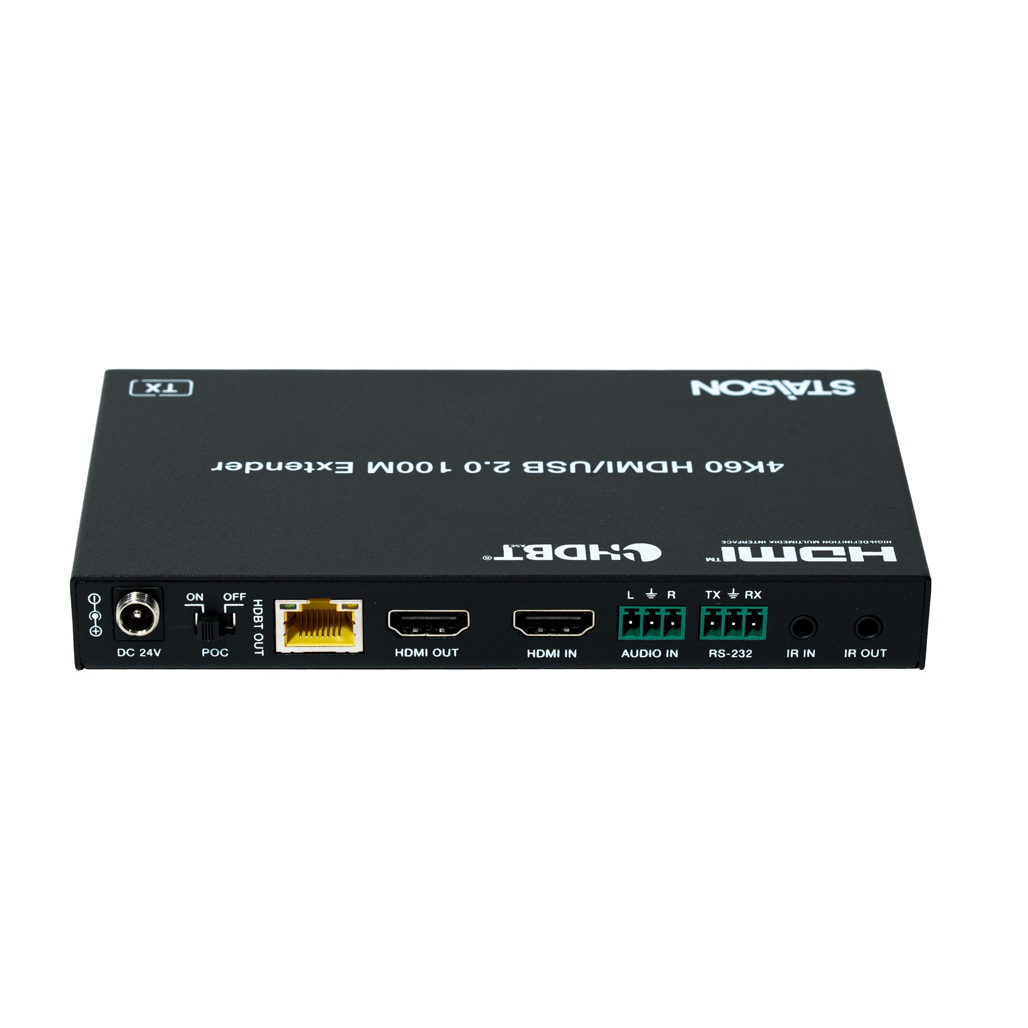
| 9 | DC 24V Port | DC 24V/1A power input port. Note: The extender supports POC function — either the Transmitter or Receiver can be powered by the 24V/1A adapter; the other unit does not require a separate power supply. |
| 10 | POC Switch | Use the switch to turn on/off POC function. |
| 11 | HDBT OUT Port | HDBaseT signal output port, connected to the HDBT IN port of Receiver with a CAT6 cable. |
| 12 | Link Signal Indicator (Green) | Light on: Transmitter and Receiver are in good connection status. Light flashing: Transmitter and Receiver are in poor connection status. Light off: Transmitter and Receiver are not connected. |
| 13 | Data Signal Indicator (Yellow) | Light flashing: There is data transmission. Light off: There is no data transmission. |
| 14 | HDMI OUT Port | HDMI loop output port, connected to HDMI display device such as TV or monitor. It loops the audio and video signal from the HDMI IN port; does not support audio embedding. |
| 15 | HDMI IN Port | HDMI signal input port, connected to HDMI source device, such as Blu-ray or PS4. |
| 16 | AUDIO IN Port | Analog audio input port for audio embedding. |
| 17 | RS-232 Port | Connected to PC or control system through 3-pin Phoenix connector for RS-232 serial command pass-through. |
| 18 | IR IN Port | Connected to IR wideband receiver cable, receiving the remote control signal and then sending it to the receiving end. |
| 19 | IR OUT Port | Connected to IR blaster cable, sending the remote control signal from the receiving end. |
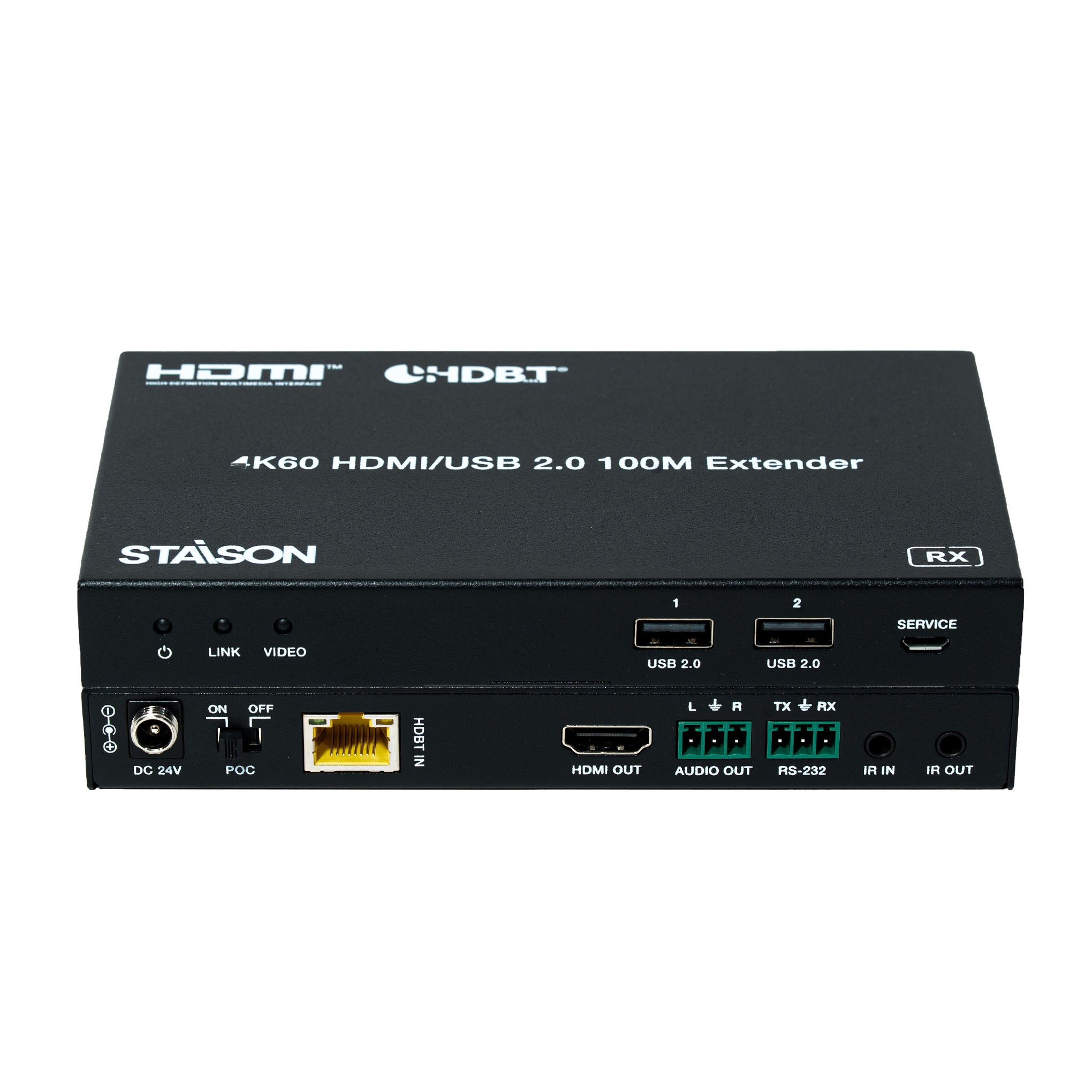
Receiver Panel

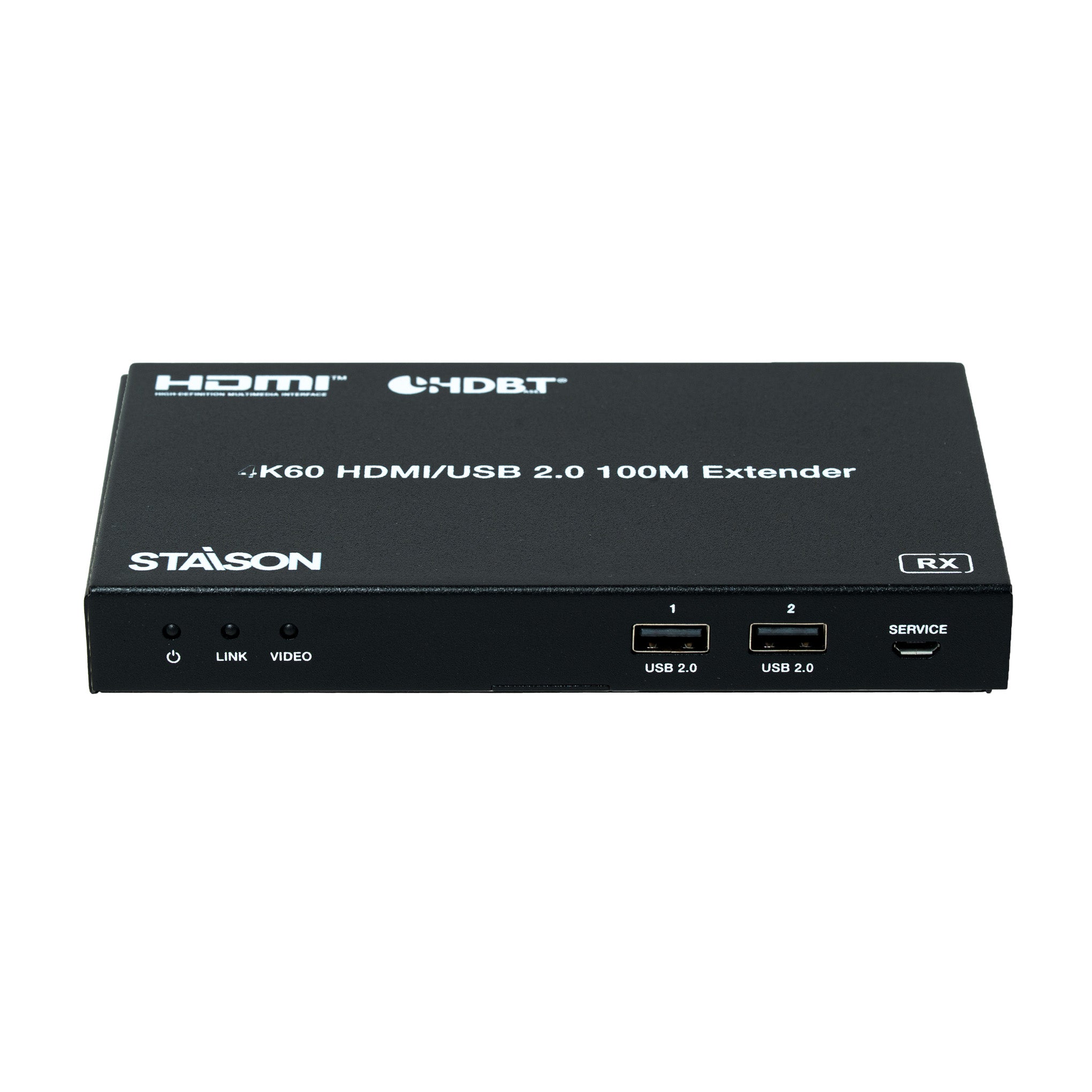
| No. | Name | Function Description |
|---|---|---|
| 1 | Power LED (Red) | Indicates the Receiver is powered on. |
| 2 | LINK LED (Green) | Light on: Transmitter and Receiver are in good connection status. Light flashing: Transmitter and Receiver are in poor connection status. Light off: Transmitter and Receiver are not connected. |
| 3 | VIDEO LED (Green) | Light flashing: There is valid signal input. Light off: There is no signal or the signal is invalid. |
| 4 | USB 2.0 Port | USB Type A ports for connecting USB 2.0 devices such as USB Flash Drive, mouse and keyboard. |
| 5 | SERVICE Port | Software update port. Send command "s switch uart 0!" to switch MCU; send command "s switch uart 1!" to switch VALENS. |
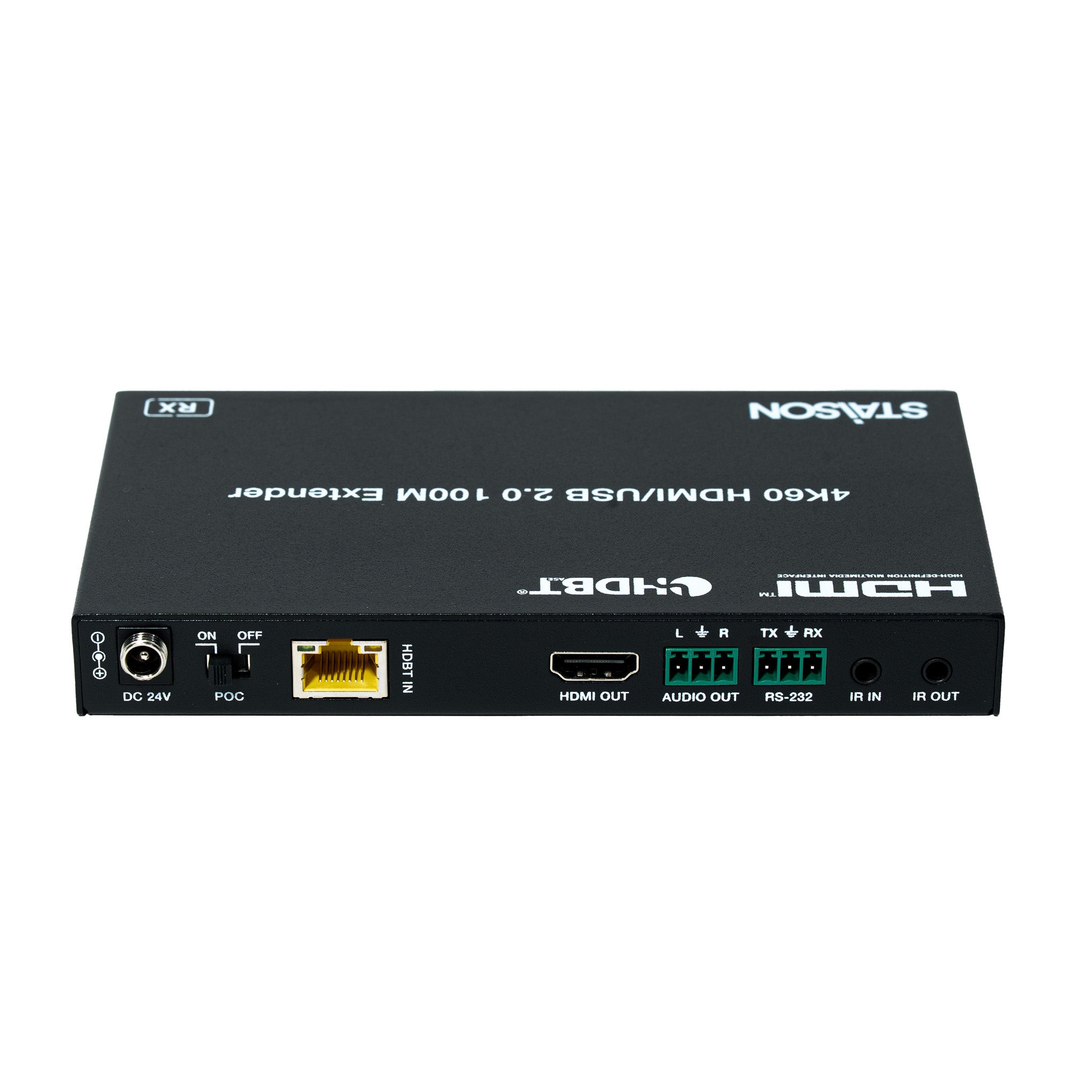
| 6 | DC 24V Port | DC 24V/1A power input port. Note: The extender supports POC function — either the Transmitter or Receiver can be powered by the 24V/1A adapter; the other unit does not require a separate power supply. |
| 7 | POC Switch | Use the switch to turn on/off POC function. |
| 8 | HDBT IN Port | HDBaseT signal input port, connected to the HDBaseT OUT port of Transmitter with a CAT6 cable. |
| 9 | Link Signal Indicator (Green) | Light on: Transmitter and Receiver are in good connection status. Light flashing: Transmitter and Receiver are in poor connection status. Light off: Transmitter and Receiver are not connected. |
| 10 | Data Signal Indicator (Yellow) | Light flashing: There is data transmission. Light off: There is no data transmission. |
| 11 | HDMI OUT port | HDMI signal output port, connected to HDMI display device such as TV or monitor. |
| 12 | AUDIO OUT port | Analog audio output port. |
| 13 | RS-232 port | Connected to PC or control system through 3-pin Phoenix connector for RS-232 serial command pass-through. |
| 14 | IR IN port | Connected to IR wideband receiver cable, receiving the remote control signal and then sending it to the transmitting end. |
| 15 | IR OUT port | Connected to IR blaster cable, sending the remote control signal from the transmitting end. |
The ST-NEHB100CN HDBaseT Extender is designed for stable professional AV signal extension over CAT6 cable.
IR Pin Definition
IR Receiver and Blaster pin definition is as below:

Note: When the angle between the IR receiver and the remote control is ±45°, the transmission distance is 0–5 meters. When the angle is ±90°, the transmission distance is 0–8 meters.
※ Description 1 — POC (Power over Cable) Application Example

※ Description 2 — Bidirectional Infrared Control Application Example

※ Description 3 — Bidirectional RS-232 Control Application Example

Application Example
