


Description
HDMI over IP Extender is based on an AV over IP solution for distribution of one HD content to one or multiple HD display devices over a standard 1G network switch, extending distance up to 150m/492ft between encoder and decoder via a CAT6 cable. It offers configurable high quality, low-bandwidth EZCast compression video. Video resolution is up to 1920×1200@60Hz. It also supports HDMI loop output on the encoder.
The product includes two units: Encoder (obtains and encodes HDMI signals, transmits via CAT6, supports HDMI loop output) and Decoder (decodes signal and outputs HDMI to HD displays). Supports one-way IR control signal transmission for the most convenient HDMI extension solution.
Features
☆ HDCP 1.4 compliant
☆ Support 6.75Gbps video bandwidth
☆ Video resolution up to 1920×1200@60Hz (HDMI 1.4)
☆ Extend transmission up to 150m/492ft via a single CAT6 cable
☆ Third-generation EZCast video transmission protocol
☆ Support 1G standard L2 switch
☆ One-way IR control signal transmission (from Decoder to Encoder)
☆ Support PCM 2.0ch — 32kHz, 44.1kHz, 48kHz, 88.2kHz, 96kHz, 176.4kHz, 192kHz
☆ HDMI loop output on Encoder
☆ Compact design for easy and flexible installation
Package Contents
① 1× HDMI over IP Extender (Encoder)
② 1× IR Blaster Cable (1.5 meters)
③ 1× 5V/1A Power Supply (Encoder)
④ 1× HDMI over IP Extender (Decoder)
⑤ 1× IR Wideband Receiver Cable (1.5 meters)
⑥ 1× 5V/1A Power Supply (Decoder)
⑦ 1× User Manual
Specifications
| Technical | |
| HDMI Compliance | HDMI 1.4 |
| HDCP Compliance | HDCP 1.4 |
| Video Bandwidth | 6.75Gbps |
| Video Resolution | Up to 1920×1200@60Hz Note: Does not support interlaced (i-standard) signals. |
| Compression Technology | EZCast |
| Color Space | RGB, YCbCr 4:4:4, YCbCr 4:2:2 |
| Color Depth | Input: 8/10/12-bit; Output: 8-bit |
| ESD Protection | IEC 61000-4-2: ±8kV (Air-gap discharge) & ±4kV (Contact discharge) |
| Audio | |
| HDMI Audio Input | PCM 2.0ch, 2.1ch, 5.1ch, 7.1ch |
| HDMI Audio Output | PCM 2.0ch |
| Sample Frequency | 32kHz, 44.1kHz, 48kHz, 88.2kHz, 96kHz, 176.4kHz, 192kHz |
| Video Network | |
| Network Bandwidth | 1G |
| Transmission Distance | 150m / 492ft |
| Switch Requirement | Transmitting data through the Data Link Layer (L2 Switch) |
| IR | |
| IR Frequency | Wideband 20Hz ~ 60kHz |
| IR Level | 5Vp-p |
| Connection – Encoder | |
| Input | 1× IN [HDMI Type A, 19-pin female] |
| Output | 1× OUT [HDMI Type A, 19-pin female] (Loop); 1× CAT OUT [RJ45] |
| Control | 1× IR OUT [3.5mm Stereo Mini-jack] |
| Connection – Decoder | |
| Input | 1× CAT IN [RJ45] |
| Output | 1× OUT [HDMI Type A, 19-pin female] |
| Control | 1× IR IN [3.5mm Stereo Mini-jack] |
| Mechanical | |
| Housing | Metal Enclosure — Black |
| Dimensions | 88mm [W] × 61.2mm [D] × 16.5mm [H] |
| Weight | Encoder: 158g; Decoder: 155g |
| Power Supply | Input: AC 100–240V 50/60Hz; Output: DC 5V/1A (US/EU, CE/FCC/UL certified) |
| Power Consumption (Max) | Encoder: 1.5W; Decoder: 1.1W |
| Environmental | |
| Operating Temperature | 0°C ~ 40°C / 32°F ~ 104°F |
| Storage Temperature | -20°C ~ 60°C / -4°F ~ 140°F |
| Relative Humidity | 20%~90% RH (non-condensing) |
Operation Controls and Functions
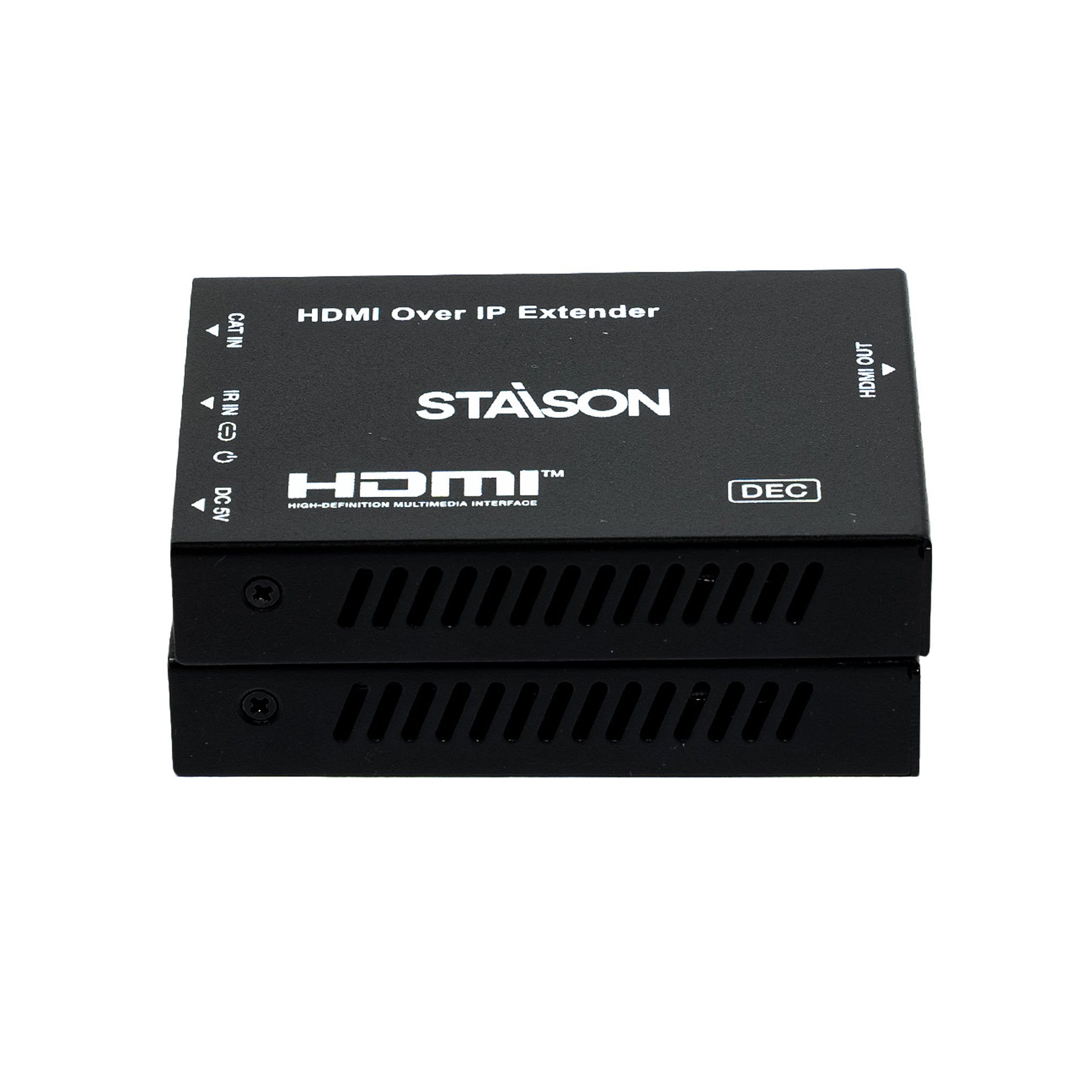
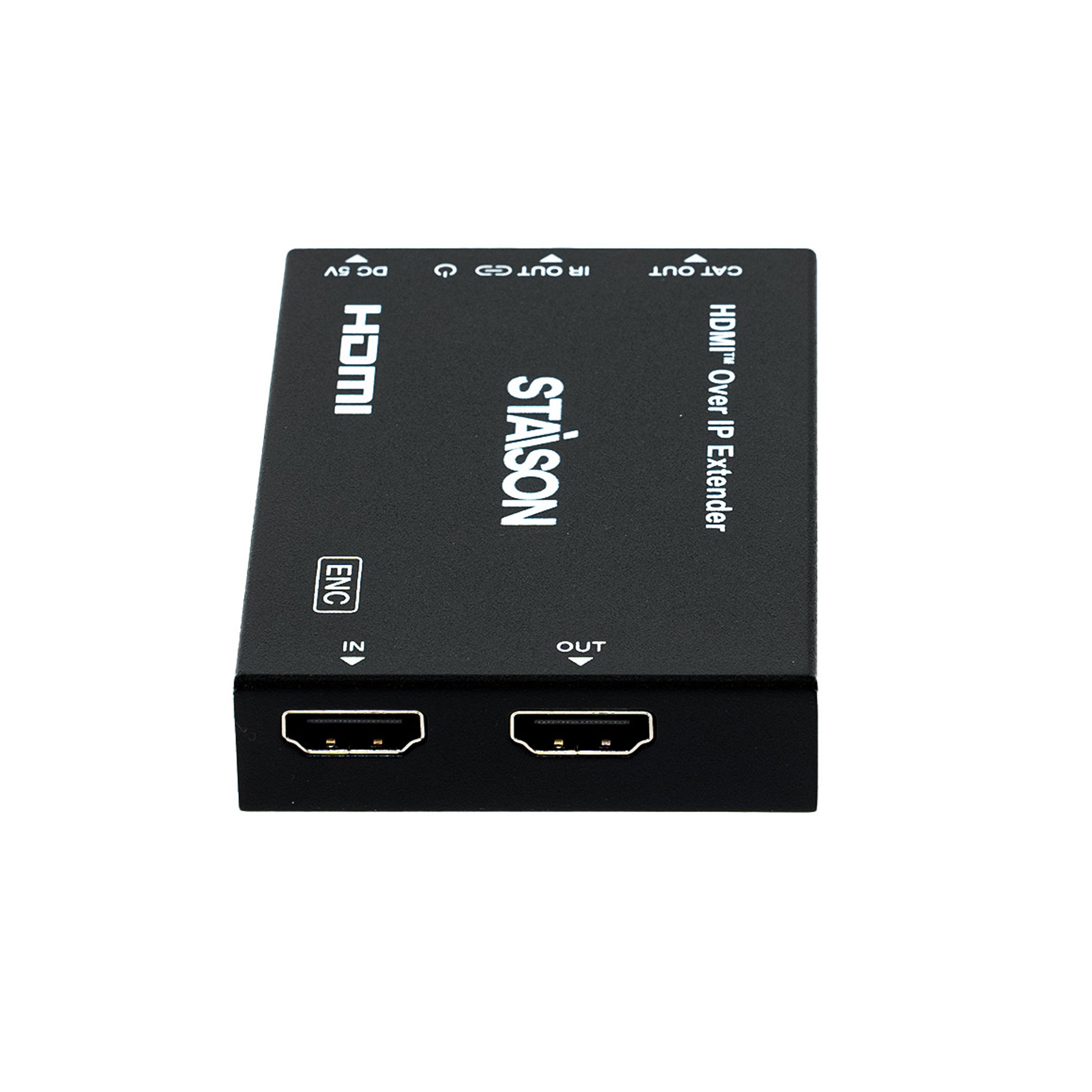
Encoder Panel

| No. | Name | Function Description |
|---|---|---|
| 1 | IN | HDMI input port — connect to HDMI source device (DVD, set-top box) with an HDMI cable. |
| 2 | OUT (Loop) | HDMI loop output port — connect to a local HDMI display device (TV, monitor) with an HDMI cable. |
| 3 | LINK LED | Blue LED flashes when Encoder is connected to Decoder or to a Switch / router / hub. |
| 4 | Power LED | Blue LED is on when the Encoder is powered on. |
| 5 | CAT OUT | Connect to the CAT IN port of Decoder or to a Switch / router / hub via CAT6 cable for sending signal to Decoder. |
| 6 | IR OUT | Connect the IR Blaster cable. The IR blaster signal comes from the IR IN port of the Decoder. |
| 7 | DC 5V | DC 5V/1A power input port. |
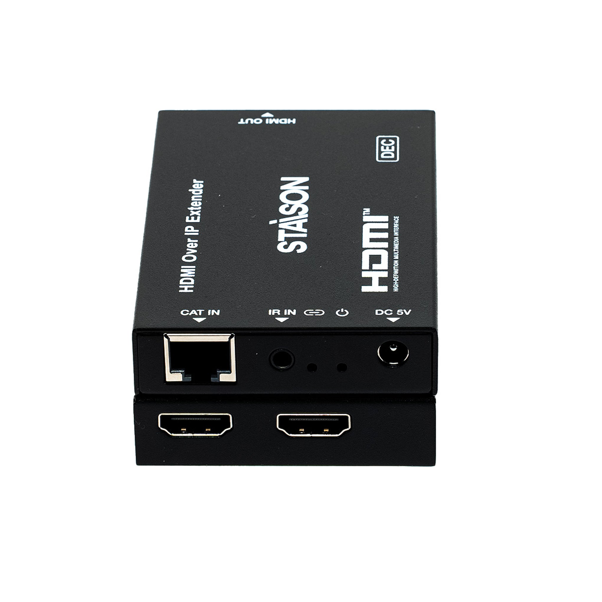
Decoder Panel

| No. | Name | Function Description |
|---|---|---|
| 1 | OUT | HDMI output port — connect to the HDMI display device (TV, monitor) with an HDMI cable. |
| 2 | CAT IN | Connect to the CAT OUT port of Encoder or to a Switch / router / hub via CAT6 cable for receiving signal from Encoder. |
| 3 | IR IN | Connect the IR Receiver cable. The IR signal is sent to the IR OUT port of the Encoder. |
| 4 | LINK LED | Blue LED flashes when Decoder is connected to Encoder or to a Switch / router / hub. |
| 5 | Power LED | Blue LED is on when the Decoder is powered on. |
| 6 | DC 5V | DC 5V/1A power input port. |
IR Pin Definition
IR Receiver and Blaster pin definition as below:

| Cable | Pin | Assignment |
|---|---|---|
| IR Blaster | Tip (Pin 1) | IR Blaster Signal |
| Ring (Pin 2) | Power (5V) | |
| Sleeve (Pin 3) | NC (No Connection) | |
| IR Receiver | Tip (Pin 1) | IR Signal |
| Ring (Pin 2) | Power (5V) | |
| Sleeve (Pin 3) | Grounding |
Application Examples
Figure 1: Point-to-Point (Encoder → Decoder directly, up to 150m)
Connect your source device (DVD/set-top box) to the Encoder's HDMI IN. The Encoder transmits the signal over a single CAT6 cable (up to 150m) to the Decoder, which outputs HDMI to the remote TV. The Encoder also provides a HDMI Loop Out for a local TV at the source location. A one-way IR control path lets you operate the source device using the remote at the display end.
Figure 2: One-to-Many via L2 Switch (1 Encoder → Multiple Decoders)
Connect the Encoder to a 1G L2 network switch via CAT6. Connect each Decoder to the same switch via individual CAT6 cables. The switch distributes the video signal to all Decoders simultaneously — each driving its own display. Ideal for digital signage, multi-room video, classrooms, and boardrooms. Each Decoder can be up to 150m from the switch.
Note: The terms HDMI and HDMI High-Definition Multimedia Interface, and the HDMI Logo are trademarks or registered trademarks of HDMI Licensing LLC in the United States and other countries.